Willkommen
Bestätigen Sie bitte Ihre Präferenzen
Einstellungen aktualisieren
Produktvorschläge
Product Family suggestions
Kennametal steht Ihnen zur Diensten
Hallo, User Name
Das von Ihnen ausgewählte Konto:
Es gibt ein Problem mit Ihrem Konto. Bitte kontaktieren Sie den Kundendienst.
Kundenkonto Konto ändern
Lieferadresse Konto ändern
- Übersicht
- Bestellungen verwalten
- Kanäle verwalten
- Adressbuch
Notifications
Mark all as read- Passwort ändern
- Mein Profil
- Abmelden
Artikel erfolgreich zum Warenkorb hinzugefügt
Warenkorb anzeigen
Warenkorb anzeigen
Mehr bekommen, weniger zahlen mit unseren zeitlich begrenzten angeboten. Jetzt bestellen
Kennametal steht Ihnen zur Diensten
Artikel erfolgreich zum Warenkorb hinzugefügt
Warenkorb anzeigen
Warenkorb anzeigen
Lösung bearbeiten
Lösung hinzufügen
Lösungsname:{{SolutionName}}- Produkte
- /
- Metallbearbeitungswerkzeuge
- /
- Fräsen
- /
- Fräsen mit Wendeschneidplatten
- /
- High-Feed-Serie
- /
- KenFeed™ 2X
- /
- KenFeed™ 2X • IC 9
- /
- Wendeschneidplatten für KenFeed™ 2X • WOEJ09....GD
Sending to {{cadTool}} in progress...
Downloaded file will be available after import in the {{cadTool}} tool library.
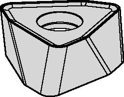
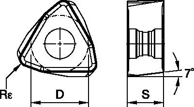
Wendeschneidplatten für KenFeed™ 2X • WOEJ09....GD
Wendeschneidplatten • WOEJ09...
Features and benefits
- Doppelseitige Wendeschneidplatte mit sechs Schneidkanten.
- Einzigartiges und stabiles Wendeschneidplattendesign für hohe Vorschübe (bis zu 2,5 mm pro Zahn).
- Die -HD-Geometrie ist die erste Wahl für Stähle, hochfeste Stähle und Gusseisen.
- Die -GD-Geometrie ermöglicht niedrigere Schnittkräfte und ist die erste Wahl für weiche Werkstoffe.
| Material Group | Light | General | Heavy | |||
| – | (Light geometry) | – | (Strong geometry) | |||
| – | wear |  | toughness | |||
| – | Geometry | Grade | Geometry | Grade | Geometry | Grade |
| P1–P2 | .S..GD | KCPK30 | .S..GD | KCPM40 | .S..HD | KCPM40 |
| P3–P4 | .S..GD | KCPK30 | .S..GD | KCPM40 | .S..HD | KCPM40 |
| P5–P6 | .S..GD | KCPK30 | .S..GD | KC725M | .S..HD | KC725M |
| M1–M2 | .S..GD | KC522M | .S..GD | KC725M | .S..HD | KC725M |
| M3 | .S..GD | KCPK30 | .S..GD | KCPM40 | .S..HD | KCPM40 |
| K1–K2 | .S..HD | KCK15 | .S..HD | KCK15 | .S..HD | KCK15 |
| K3 | .S..GD | KCPK30 | .S..HD | KCK15 | .S..HD | KCPK30 |
| N1–N2 | – | – | – | – | – | – |
| N3 | – | – | – | – | – | – |
| S1–S2 | .S..GD | KC522M | .S..GD | KC725M | .S..HD | KC725M |
| S3 | .S..GD | KC725M | .S..GD | KCPM40 | .S..HD | KCPM40 |
| S4 | .S..GD | KC522M | .S..HD | KC522M | .S..HD | KC725M |
| H1 | – | – | – | – | – | – |
Insert Selection Guide
| Material Group | Light | General | Heavy | |||
| (Light geometry) | (Strong geometry) | |||||
| wear | | toughness | ||||
| Geometry | Grade | Geometry | Grade | Geometry | Grade | |
| P1–P2 | .S..GD | KCPK30 | .S..GD | KCPM40 | .S..HD | KCPM40 |
| P3–P4 | .S..GD | KCPK30 | .S..GD | KCPM40 | .S..HD | KCPM40 |
| P5–P6 | .S..GD | KCPK30 | .S..GD | KC725M | .S..HD | KC725M |
| M1–M2 | .S..GD | KC522M | .S..GD | KC725M | .S..HD | KC725M |
| M3 | .S..GD | KCPK30 | .S..GD | KCPM40 | .S..HD | KCPM40 |
| K1–K2 | .S..HD | KCK15 | .S..HD | KCK15 | .S..HD | KCK15 |
| K3 | .S..GD | KCPK30 | .S..HD | KCK15 | .S..HD | KCPK30 |
| N1–N2 | – | – | – | – | – | – |
| N3 | – | – | – | – | – | – |
| S1–S2 | .S..GD | KC522M | .S..GD | KC725M | .S..HD | KC725M |
| S3 | .S..GD | KC725M | .S..GD | KCPM40 | .S..HD | KCPM40 |
| S4 | .S..GD | KC522M | .S..HD | KC522M | .S..HD | KC725M |
| H1 | – | – | – | – | – | – |
Empfohlene Startwerte für Vorschübe [mm]
| Insert Geometry | Recommended Starting Feed per Tooth (Fz) in Relation to % of Radial Engagement (ae) | Insert Geometry | ||||||||||||||
| 5% | 10% | 20% | 30% | 40–100% | ||||||||||||
| .S..GD | 1,15 | 2,42 | 3,84 | 0,82 | 1,71 | 2,67 | 0,61 | 1,26 | 1,96 | 0,53 | 1,10 | 1,70 | 0,49 | 1,01 | 1,55 | .S..GD |
| .S..HD | 1,15 | 2,78 | 4,27 | 0,82 | 1,96 | 2,94 | 0,61 | 1,44 | 2,16 | 0,53 | 1,26 | 1,87 | 0,49 | 1,15 | 1,71 | .S..HD |
| Light | General | Heavy |
Recommended Starting Feeds [IPT]
| Light | General | Heavy |
| Insert Geometry | Recommended Starting Feed per Tooth (Fz) in Relation to % of Radial Engagement (ae) | Insert Geometry | ||||||||||||||
| 5% | 10% | 20% | 30% | 40–100% | ||||||||||||
| .S..GD | .045 | .089 | .141 | .032 | .063 | .098 | .024 | .047 | .072 | .021 | .040 | .063 | .019 | .037 | .057 | .S..GD |
| .S..HD | .045 | .109 | .168 | .032 | .077 | .116 | .024 | .057 | .085 | .021 | .049 | .074 | .019 | .045 | .067 | .S..HD |
Empfohlene Startwerte für Schnittgeschwindigkeiten [m/min]
| Material Group | KC522M | KC725M | KCK15 | KCPK30 | |||||||||
| P | 1 | 395 | 345 | 325 | 315 | 275 | 255 | – | – | – | 545 | 475 | 440 |
| 2 | 330 | 290 | 240 | 260 | 230 | 195 | – | – | – | 335 | 305 | 275 | |
| 3 | 305 | 255 | 215 | 240 | 205 | 170 | – | – | – | 305 | 275 | 250 | |
| 4 | 270 | 225 | 180 | 215 | 180 | 145 | – | – | – | 225 | 210 | 190 | |
| 5 | 225 | 200 | 180 | 180 | 160 | 145 | – | – | – | 310 | 275 | 255 | |
| 6 | 200 | 150 | 120 | 160 | 120 | 95 | – | – | – | 190 | 165 | – | |
| M | 1 | 245 | 215 | 200 | 205 | 180 | 165 | – | – | – | 250 | 220 | 190 |
| 2 | 225 | 190 | 160 | 185 | 160 | 130 | – | – | – | 225 | 195 | 170 | |
| 3 | 170 | 145 | 115 | 140 | 120 | 95 | – | – | – | 175 | 160 | 140 | |
| K | 1 | 275 | 250 | 220 | – | – | – | 505 | 460 | 410 | 355 | 320 | 285 |
| 2 | 215 | 195 | 180 | – | – | – | 400 | 355 | 330 | 280 | 255 | 230 | |
| 3 | 180 | 160 | 145 | – | – | – | 335 | 300 | 275 | 235 | 210 | 195 | |
| N | 1 | – | – | – | – | – | – | – | – | – | – | – | – |
| 2 | – | – | – | – | – | – | – | – | – | – | – | – | |
| S | 1 | 50 | 45 | 35 | 45 | 35 | 30 | – | – | – | – | – | – |
| 2 | 50 | 45 | 35 | 45 | 35 | 30 | – | – | – | – | – | – | |
| 3 | 60 | 50 | 35 | 55 | 45 | 30 | – | – | – | – | – | – | |
| 4 | 85 | 60 | 45 | 75 | 55 | 35 | – | – | – | – | – | – | |
| H | 1 | 145 | 110 | 85 | – | – | – | – | – | – | – | – | – |
| 2 | – | – | – | – | – | – | – | – | – | – | – | – | |
| 3 | – | – | – | – | – | – | – | – | – | – | – | – | |
Maximalwerte für lineares und spiralförmige Interpolation in das volle Material • Zoll
| cutter type | catalog number | recommended ramping angle (for continuous ramping process) | max ramp angle when Ap max (not for continuous ramping process) | max ramp angle for 360° helical interpolation | min hole diameter (DH min) | max flat-bottom hole diameter (DH1 max) | max diameter (no flat bottom) |
| Screw-On | KF2X100W0902M12L138 | 3.5° | 5.2° | 3.1° | 1.291 | 1.35 | 2.0 |
| KF2X125W0902M16L169 | 1.9° | 2.8° | 1.7° | 1.813 | 1.87 | 2.5 | |
| KF2X125W0903M16L169 | 1.9° | 2.8° | 1.7° | 1.813 | 1.87 | 2.5 | |
| KF2X150W0903M16L169 | 1.4° | 2.1° | 1.2° | 2.310 | 2.37 | 3.0 | |
| KF2X150W0904M16L169 | 1.4° | 2.1° | 1.2° | 2.310 | 2.37 | 3.0 | |
| End Mills | KF2X100W0902C100L600 | 3.5° | 5.2° | 3.1° | 1.291 | 1.35 | 2.0 |
| KF2X100W0902C100L800 | 3.5° | 5.2° | 3.1° | 1.291 | 1.35 | 2.0 | |
| KF2X125W0903C125L600 | 1.9° | 2.8° | 1.7° | 1.813 | 1.87 | 2.5 | |
| KF2X125W0903C125L800 | 1.9° | 2.8° | 1.7° | 1.813 | 1.87 | 2.5 | |
| KF2X150W0903C125L600 | 1.4° | 2.1° | 1.2° | 2.310 | 2.37 | 3.0 | |
| KF2X150W0903C125L800 | 1.4° | 2.1° | 1.2° | 2.310 | 2.37 | 3.0 | |
| Face Mills | KF2X150W0904S050L157 | 1.4° | 2.1° | 1.2° | 2.310 | 2.37 | 3.0 |
| KF2X200W0905S075L157 | 1.0° | 1.4° | 0.8° | 3.307 | 3.37 | 4.0 | |
| KF2X200W0906S075L157 | 1.0° | 1.4° | 0.8° | 3.307 | 3.37 | 4.0 | |
| KF2X250W0906S075L175 | 0.7° | 1.1° | 0.6° | 4.305 | 4.36 | 5.0 | |
| KF2X300W0907S100L175 | 0.6° | 1.0° | 0.5° | 5.303 | 5.36 | 6.0 | |
| KF2X300W0907S125L200 | 0.6° | 1.0° | 0.5° | 5.303 | 5.36 | 6.0 |
General Programming Information for Applying KenFeed 2X • IC 09
| Rt | Wt | t |
| .110 | .312 | .045 |
Maximalwerte für lineares und spiralförmige Interpolation in das volle Material • Zoll
| cutter type | catalog number | recommended ramping angle (for continuous ramping process) | max ramp angle when Ap max (not for continuous ramping process) | max ramp angle for 360° helical interpolation | min hole diameter (DH min) | max flat-bottom hole diameter (DH1 max) | max diameter (no flat bottom) |
| Screw-On | KF2X2X25Z02M12WO09 | 3.6° | 5.4° | 3.1° | 26,5 | 33,7 | 50 |
| KF2X32Z03M16WO09 | 1.8° | 2.7° | 1.7° | 41,2 | 48,4 | 64 | |
| KF2X35Z03M16WO09 | 1.6° | 2.4° | 1.4° | 46,8 | 54,0 | 70 | |
| KF2X42Z04M16WO09 | 1.2° | 1.9° | 0.8° | 68,7 | 75,9 | 84 | |
| End Mills | KF2X25Z02A25WO09L140 | 3.6° | 5.4° | 3.1° | 26,5 | 33,7 | 50 |
| KF2X25Z02A25WO09L200 | 3.6° | 5.4° | 3.1° | 26,5 | 33,7 | 50 | |
| KF2X25Z02A25WO09L300 | 3.6° | 5.4° | 3.1° | 26,5 | 33,7 | 50 | |
| KF2X28Z02A25WO09L200 | 3.1° | 4.6° | 2.5° | 31,6 | 38,8 | 56 | |
| KF2X32Z03A32WO09L150 | 1.8° | 2.7° | 1.7° | 41,2 | 48,4 | 64 | |
| KF2X32Z03A32WO09L200 | 1.8° | 2.7° | 1.7° | 41,2 | 48,4 | 64 | |
| KF2X32Z03A32WO09L300 | 1.8° | 2.7° | 1.7° | 41,2 | 48,4 | 64 | |
| KF2X35Z03A32WO09L200 | 1.6° | 2.4° | 1.4° | 46,8 | 54,0 | 70 | |
| Face Mills | KF2X40Z04WO09 | 1.3° | 2.0° | 1.2° | 56,4 | 63,6 | 80 |
| KF2X50Z05WO09 | 1.0° | 1.5° | 0.8° | 76,7 | 83,9 | 100 | |
| KF2X52Z05WO09 | 1.0° | 1.4° | 0.8° | 80,7 | 87,9 | 104 | |
| KF2X63Z05S22WO09 | 0.8° | 1.2° | 0.6° | 102,7 | 109,9 | 126 | |
| KF2X63Z05WO09 | 0.8° | 1.2° | 0.6° | 102,7 | 109,9 | 126 | |
| KF2X66Z06S22WO09 | 0.7° | 1.1° | 0.5° | 108,7 | 115,9 | 132 | |
| KF2X66Z06WO09 | 0.7° | 1.1° | 0.5° | 108,7 | 115,9 | 132 | |
| KF2X80Z07WO09 | 0.6° | 0.9° | 0.4° | 136,6 | 143,8 | 160 |
Maximalwerte für lineares und spiralförmige Interpolation in das volle Material • Zoll
| diameter | max ramp angle | max ramp angle for 360° helical interpolation | max plunge depth | min hole diameter (DH min) | max flat-bottom hole diameter (DH1 max) | max diameter (no flat bottom) |
| 1.50 | 5.5° | 1.93° | 0.076 | 1.90 | 2.22 | 3.00 |
| 2.00 | 4.4° | 1.18° | 0.076 | 2.86 | 3.22 | 4.00 |
| 2.50 | 3.0° | 0.85° | 0.076 | 3.85 | 4.22 | 5.00 |
| 3.00 | 2.3° | 0.67° | 0.076 | 4.84 | 5.21 | 6.00 |
| 4.00 | 1.6° | 0.47° | 0.076 | 6.84 | 7.21 | 8.00 |
| 5.00 | 1.2° | 0.36° | 0.076 | 8.84 | 9.21 | 10.00 |