Prodotto simile a :
KVNS™ A2™ • Arbor Mount • Inch
Slot milling cutter for multiple materials
Material Number1247790
ISO Catalog IDKVNS121970DANSI Catalog IDKVNS121970D
Scanalatura: Lato con dimensioni AE/AP
Sending to {{cadTool}} in progress...
Downloaded file will be available after import in the {{cadTool}} tool library.

| Material Number | 1247790 |
| ISO Catalog ID | KVNS121970D |
| ANSI Catalog ID | KVNS121970D |
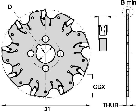
| [BM] Larghezza minima di taglio | 5.232 mm |
| [BM] Larghezza minima di taglio | 0.206 in |
| [D1] Diametro di taglio effettivo | 304.8 mm |
| [D1] Diametro di taglio effettivo | 12 in |
| [CDX] Massima profondità di taglio radiale | 81.026 mm |
| [CDX] Massima profondità di taglio radiale | 3.19 in |
| [D] Dia adattatore / stelo / foro | 50.8 mm |
| [D] Dia adattatore / stelo / foro | 2 in |
| [THUB] Spessore mozzo | 4.4 mm |
| [THUB] Spessore mozzo | 0.1732 in |
| Numero di inserti | 30 |
| Inserto di riferimento | OD_5197__ |
| Max giri/min | 1050 |
Uses and application
Scanalatura: Lato con dimensioni AE/AP
Features and benefits
- Self-clamping insert seat with fixed stop.
- Excellent for all flat-bottom slotting and cut-off operations.
- Two drive rings required for each cutter body. They must be ordered separately, and in pairs of two.
- For cutter diameters 8" and 10" support rings are optional (instead of drive rings). Support rings also must be ordered separately, and in pairs of two.
Crea una soluzione per calcolare avanzamenti e velocità
Dopo aver creato una soluzione, basta scegliere l'icona Avanzamento e Velocità e il nostro sistema fornirà dei suggerimenti. Puoi personalizzare le informazioni aggiungendo la tua macchina e le specifiche o apportare delle modifiche utilizzando i cursori.
Feeds
Avanzamenti iniziali consigliati [mm]
| KVNS™ A2™ Series • Recommended Starting Feeds [mm/th] | |||||||||||||||
| Geometria dell'inserto | Avanzamento per dente programmato (fz) in base alla % della profondità di taglio radiale (ae) | ||||||||||||||
| 5% | 10% | 20% | 30% | 40–100% | |||||||||||
| L | M | H | L | M | H | L | M | H | L | M | H | L | M | H | |
| .S..GD | 0,23 | 0,46 | 0,71 | 0,17 | 0,33 | 0,51 | 0,13 | 0,25 | 0,38 | 0,11 | 0,22 | 0,33 | 0,10 | 0,20 | 0,30 |
| .S..GB | 0,23 | 0,46 | 0,74 | 0,17 | 0,33 | 0,54 | 0,13 | 0,25 | 0,40 | 0,11 | 0,22 | 0,35 | 0,10 | 0,20 | 0,32 |
| L = Light Machining; M = Medium Machining; H = Heavy Machining NOTE: Use "Light Machining" values as starting feed rate. | |||||||||||||||
Recommended Starting Feeds [IPT]
| KVNS™ A2™ Series • Recommended Starting Feeds [IPT] | |||||||||||||||
| Geometria dell'inserto | Avanzamento per dente programmato (fz) in base alla % della profondità di taglio radiale (ae) | ||||||||||||||
| 5% | 10% | 20% | 30% | 40–100% | |||||||||||
| L | M | H | L | M | H | L | M | H | L | M | H | L | M | H | |
| .S..GD | 0.009 | 0.017 | 0.026 | 0.007 | 0.013 | 0.019 | 0.005 | 0.009 | 0.014 | 0.004 | 0.008 | 0.012 | 0.004 | 0.008 | 0.011 |
| .S..GB | 0.009 | 0.017 | 0.028 | 0.007 | 0.013 | 0.020 | 0.005 | 0.009 | 0.015 | 0.004 | 0.008 | 0.013 | 0.004 | 0.008 | 0.012 |
| L = Light Machining; M = Medium Machining; H = Heavy Machining NOTE: Use "Light Machining" values as starting feed rate. | |||||||||||||||
Speeds
Velocità iniziali consigliate [m/min]
| KVNS™ A2™ Series • Recommended Starting Speed [m/min] | |||||||
| Qualità | KCPK30 | KMF | |||||
| Spessore truciolo hex mm | Min | Max | Min | Max | |||
| Gruppo materiali | Max | Valore Iniziale | Min | Max | Valore Iniziale | Min | |
| P | 1 | 455 | 395 | 370 | – | – | – |
| 2 | 280 | 255 | 230 | – | – | – | |
| 3 | 255 | 230 | 205 | – | – | – | |
| 4 | 225 | 185 | 160 | – | – | – | |
| 5 | 190 | 170 | 150 | – | – | – | |
| 6 | 160 | 135 | 110 | – | – | – | |
| M | 1 | 205 | 185 | 155 | – | – | – |
| 2 | 185 | 160 | 140 | – | – | – | |
| 3 | 145 | 130 | 115 | – | – | – | |
| K | 1 | 295 | 265 | 240 | – | – | – |
| 2 | 235 | 210 | 190 | – | – | – | |
| 3 | 195 | 175 | 160 | – | – | – | |
| N | 1 | – | – | – | 335 | 298 | 271 |
| 2 | – | – | – | 335 | 298 | 271 | |
| 3 | – | – | – | 219 | 198 | 170 | |
| S | 1 | – | – | – | 30 | 24 | 20 |
| 2 | – | – | – | 30 | 24 | 20 | |
| 3 | – | – | – | 30 | 24 | 20 | |
| 4 | 50 | 45 | 35 | 24 | 24 | 24 | |
| H | 1 | – | – | – | – | – | – |
| Recommended Starting Speed are pointing to 90° Shoulder Milling . Starting Speed for Face and Copy Milling can be Increased by 20 %. As the average chip thickness increases, speed should be decreased. Material groups P, M, K and H show recommended starting speeds for dry machining. For wet machining, reduce speed by 20%. Material groups N and S show recommended starting speeds for wet machining. Not recommended for dry machining. | |||||||
Recommended Starting Speeds [SFM]
| KVNS™ A2™ Series • Recommended Starting Speed [SFM] | |||||||
| Qualità | KCPK30 | KMF | |||||
| Chip Thickness hex Inch | Min | Max | Min | Max | |||
| Gruppo materiali | Max | Valore Iniziale | Min | Max | Valore Iniziale | Min | |
| P | 1 | 1495 | 1295 | 1215 | – | – | – |
| 2 | 920 | 835 | 755 | – | – | – | |
| 3 | 835 | 755 | 675 | – | – | – | |
| 4 | 740 | 605 | 525 | – | – | – | |
| 5 | 625 | 560 | 490 | – | – | – | |
| 6 | 525 | 445 | 360 | – | – | – | |
| M | 1 | 675 | 605 | 510 | – | – | – |
| 2 | 605 | 525 | 460 | – | – | – | |
| 3 | 475 | 425 | 375 | – | – | – | |
| K | 1 | 970 | 870 | 785 | – | – | – |
| 2 | 770 | 690 | 625 | – | – | – | |
| 3 | 640 | 575 | 525 | – | – | – | |
| N | 1 | – | – | – | 1100 | 980 | 890 |
| 2 | – | – | – | 1100 | 980 | 890 | |
| 3 | – | – | – | 720 | 650 | 560 | |
| S | 1 | – | – | – | 100 | 80 | 65 |
| 2 | – | – | – | 100 | 80 | 65 | |
| 3 | – | – | – | 100 | 80 | 65 | |
| 4 | 165 | 150 | 115 | 80 | 80 | 80 | |
| H | 1 | – | – | – | – | – | – |
| Recommended Starting Speed are pointing to 90° Shoulder Milling . Starting Speed for Face and Copy Milling can be Increased by 20 %. As the average chip thickness increases, speed should be decreased. Material groups P, M, K and H show recommended starting speeds for dry machining. For wet machining, reduce speed by 20%. Material groups N and S show recommended starting speeds for wet machining. Not recommended for dry machining. | |||||||
Insert Selection
Guida alla selezione degli inserti
| KVNS™ A2™ Slotting Cutters • Insert Selection Guide | ||||||
| Gruppo materiali | Lavorazione leggera | Uso generico | Lavorazione pesante | |||
| – | (Geometria leggera) | (Geometria robusta) | ||||
| – | resistenza all’usura |  | tenacità | |||
| – | Geometria | Qualità | Geometria | Qualità | Geometria | Qualità |
| P1-P2 | .S..GD | KCPK30 | .S..GD | KCPK30 | .S..GB | KCPK30 |
| P3-P4 | .S..GD | KCPK30 | .S..GD | KCPK30 | .S..GB | KCPK30 |
| P5-P6 | .S..GD | KCPK30 | .S..GB | KCPK30 | .S..GB | KCPK30 |
| M1-M2 | .S..GD | KCPK30 | .S..GD | KCPK30 | .S..GB | KCPK30 |
| M3 | .S..GD | KCPK30 | .S..GB | KCPK30 | .S..GB | KCPK30 |
| K1-K2 | .S..GD | KCPK30 | .S..GD | KCPK30 | .S..GB | KCPK30 |
| K3 | .S..GD | KCPK30 | .S..GD | KCPK30 | .S..GB | KCPK30 |
| N1-N2 | – | – | – | – | – | – |
| N3 | – | – | – | – | – | – |
| S1-S2 | – | – | – | – | – | – |
| S3 | – | – | – | – | – | – |
| S4 | – | – | – | – | – | – |
| H1 | – | – | – | – | – | – |
I have read and accepted the Terms & Conditions of use


