Welcome
Please confirm your preferences
Update Preferences
Product Suggestions
Product Family suggestions
Hi, Sign In
Your Selected Account:
There is an issue with your account. Please contact customer support.
Sold To Account Change Account
Ship To Account Change Account
Take advantage of these exclusive deals before it is too late! See Promotions
- Products
- /
- Metalworking Tools
- /
- Turning
- /
- Cut-Off, Groove and Turn
- /
- Cut-Off
- /
- A2™ • Single-Ended Cut-Off
A2™ • Single-Ended Cut-Off
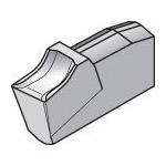
If your machining operations depend on accurate single-ended cut-off tools, you can immediately improve your processes with A2 cut-off tools. These solid carbide tools are optimal for high-speed applications with cast iron, non-ferrous metals, and other tough workpiece materials. When you use cut-off tools from Kennametal's A2 line, you achieve consistency while reducing downtime with inferior tools. If you have questions about our A2 line or need a specialty tool, our design team is ready to assist.
Select Filters
Filters
Filters
View filters in
Metric
Inch
Key Filters
Workpiece Material
Workpiece Material
- P Steel (252)
- P0Low-Carbon Steels, Long Chipping C < .25%; <125 HB; <530 N/mm^2 UTS(252)
- P1Low-Carbon Steels, Short Chipping C < .25%; <125 HB; <530 N/mm^2 UTS(252)
- P2Medium and High Carbon Steels C < .25%; <220 HB; <25 HRC; >530 N/mm^2 UTS(252)
- P3Alloy Steels & Tool Steels C > .25%; <330 HB; <35 HRC; 600-850 N/mm^2 UTS(252)
- P4Alloy Steels & Tool Steels C > .25%; 350-420 HB; 35-43 HRC; 850-1400 N/mm^2 UTS(252)
- P5Ferritic, Martensitic, and PH Stainless Steels <330 HB; <35 HRC; 600-900 N/mm^2 UTS(252)
- P6High Strength Ferritic, Martensitic, and PH Stainless Steels 350-450 HB; 35-43 HRC; 900-2400 N/mm^2 UTS(252)
- M Stainless Steel (253)
- M1Austenitic Stainless Steel 130-200 HB; <600 N/mm^2 UTS(253)
- M2High Strength Austenitic Stainless and Cast Stainless Steels 150-230 HB; <25 HRC; >600 N/mm^2 UTS(253)
- M3Duplex Stainless Steel 135-275 HB; <30 HRC; 500-1200 N/mm^2 UTS(253)
- K Cast Iron (244)
- K1Gray Cast Iron 120-290 HB; <32 HRC; 125-500 N/mm^2 UTS(244)
- K2Low and Medium Strength CGI and Ductile Irons 130-260 HB; <28 HRC; <600 N/mm^2 UTS(244)
- K3High Strength Ductile and Austempered Ductile Iron 180-350 HB; <43 HRC; >600 N/mm^2 UTS(244)
- N Non-Ferrous Materials (244)
- N1Wrought Aluminum (244)
- N2Low-Silicon Aluminum Alloys and Magnesium Alloys Si <12.2%(243)
- N4Copper, Brass, Zinc-based on machinability index range of 70-100 (244)
- N5Nylon, Plastics, Rubbers, Phenolics, Resins, Fiberglass (243)
- N6Carbon, Graphite Composites, CFRP (243)
- S High-Temp Alloys (244)
- S1Iron-Based, Heat-Resistant Alloys 160-260 HB; 25-48 HRC; 500-1200 N/mm^2 UTS(244)
- S2Cobalt-Based, Heat-Resistant Alloys 250-450 HB; 25-48 HRC; 1000-1450 N/mm^2 UTS(244)
- S3Nickel-Based, Heat Resistant Alloys 160-450 HB; <48 HRC; 600-1700 N/mm^2 UTS(244)
- S4Titanium and Titanium Alloys 300-400 HB; 33-43 HRC; 900-1600 N/mm^2 UTS(244)
Applications
Applications
Cut-Off (253)
Face Grooving (63)
Grooving (63)
ID Grooving (63)
Cutting Condition
Cutting Condition
- Heavily Interrupted Cut (208)
- Lightly Interrupted Cut (244)
- Smooth Cut (253)
- Varying Depth of Cut (244)
=
Tool Cutting Edge Angle
Tool Cutting Edge Angle
- 90.0 (75)
Tool Cutting Edge Angle MinEnter ValuetoTool Cutting Edge Angle MaxTool Cutting Edge Angle
Connection Style
Connection Style
- Cutoff Support Blade A1-A3 (35)
- Toolholder (40)
=
Cutting Edges Per Insert
Cutting Edges Per Insert
- 1.0 (253)
Cutting Edges Per Insert MinEnter ValuetoCutting Edges Per Insert MaxCutting Edges Per Insert
Internal Coolant Capability
Internal Coolant Capability
=
Over All Length [L]
Over All Length [L]
- 2.953 in(2)
- 3.386 in(7)
- 3.396 in(2)
- 3.551 in(2)
- 3.553 in(1)
- 3.946 in(1)
- 4.331 in(20)
- 4.339 in(2)
- 4.341 in(11)
- 4.343 in(1)
- 4.5 in(5)
- 4.921 in(8)
- 4.931 in(4)
- 5.0 in(6)
- 5.118 in(6)
- 5.315 in(3)
- 5.906 in(3)
- 5.913 in(3)
- 5.915 in(4)
- 5.917 in(2)
- 6.0 in(4)
- 10.242 in(1)
Over All Length [L] MinEnter ValuetoOver All Length [L] MaxOver All Length [L]
=
Over All Length [L]
Over All Length [L]
- 75.0 mm(2)
- 86.0 mm(7)
- 86.25 mm(2)
- 90.2 mm(2)
- 90.25 mm(1)
- 100.2 mm(1)
- 110.0 mm(20)
- 110.2 mm(2)
- 110.25 mm(11)
- 110.301 mm(1)
- 114.301 mm(5)
- 125.0 mm(8)
- 125.25 mm(4)
- 127.0 mm(6)
- 130.0 mm(6)
- 135.0 mm(3)
- 150.0 mm(3)
- 150.201 mm(3)
- 150.25 mm(4)
- 150.3 mm(2)
- 152.4 mm(4)
- 260.151 mm(1)
Over All Length [L] MinEnter ValuetoOver All Length [L] MaxOver All Length [L]
Corner configuration
≈
Corner Radius
Corner Radius
- 0.004 in(51)
- 0.006 in(22)
- 0.008 in(121)
- 0.012 in(92)
- 0.016 in(15)
Corner Radius MinEnter ValuetoCorner Radius MaxCorner Radius
≈
Corner Radius
Corner Radius
- 0.1 mm(51)
- 0.151 mm(22)
- 0.2 mm(121)
- 0.301 mm(92)
- 0.4 mm(15)
Corner Radius MinEnter ValuetoCorner Radius MaxCorner Radius
=
Corner Chamfer
Corner Chamfer
- 0.0 mm(178)
Corner Chamfer MinEnter ValuetoCorner Chamfer MaxCorner Chamfer
=
Corner Chamfer
Corner Chamfer
- 0.0 in(178)
Corner Chamfer MinEnter ValuetoCorner Chamfer MaxCorner Chamfer
Application
Grade Of Cutting Tool
Grade Of Cutting Tool
- KC5025 (124)
- KCU25 (131)
- KCU25B (138)
- KMF (31)
- KT315 (77)
Hand Of Tool
Hand Of Tool
- L (24)
- N (21)
- R (30)
Wiper Insert
Wiper Insert
- N (253)
=
F Dimension
F Dimension
- 1.25 mm(2)
- 9.625 mm(2)
- 10.125 mm(1)
- 12.125 mm(1)
- 12.201 mm(4)
- 12.351 mm(4)
- 12.8 mm(2)
- 12.925 mm(2)
- 16.2 mm(2)
- 16.35 mm(2)
- 19.151 mm(1)
- 19.401 mm(4)
- 20.1 mm(1)
- 20.201 mm(2)
- 20.25 mm(1)
- 20.35 mm(4)
- 25.3 mm(2)
- 25.35 mm(1)
- 25.75 mm(4)
F Dimension MinEnter ValuetoF Dimension MaxF Dimension
=
F Dimension
F Dimension
- 0.049 in(2)
- 0.379 in(2)
- 0.399 in(1)
- 0.478 in(1)
- 0.48 in(4)
- 0.486 in(4)
- 0.504 in(2)
- 0.509 in(2)
- 0.638 in(2)
- 0.644 in(2)
- 0.754 in(1)
- 0.764 in(4)
- 0.791 in(1)
- 0.795 in(2)
- 0.797 in(1)
- 0.801 in(4)
- 0.996 in(2)
- 0.998 in(1)
- 1.014 in(4)
F Dimension MinEnter ValuetoF Dimension MaxF Dimension
=
Maximum Axial Groove Diameter
Maximum Axial Groove Diameter
- 0.787 in(6)
- 0.79 in(6)
- 1.181 in(3)
- 1.339 in(1)
- 1.496 in(1)
- 1.651 in(1)
- 1.655 in(14)
- 1.772 in(2)
- 2.047 in(6)
- 2.05 in(2)
- 2.44 in(6)
- 2.441 in(4)
- 2.48 in(2)
- 2.598 in(4)
Maximum Axial Groove Diameter MinEnter ValuetoMaximum Axial Groove Diameter MaxMaximum Axial Groove Diameter
=
Maximum Axial Groove Diameter
Maximum Axial Groove Diameter
- 20.0 mm(6)
- 20.076 mm(6)
- 30.0 mm(3)
- 34.0 mm(1)
- 38.0 mm(1)
- 41.901 mm(1)
- 42.0 mm(14)
- 45.0 mm(2)
- 52.0 mm(6)
- 52.075 mm(2)
- 61.975 mm(6)
- 62.0 mm(4)
- 63.0 mm(2)
- 66.0 mm(4)
Maximum Axial Groove Diameter MinEnter ValuetoMaximum Axial Groove Diameter MaxMaximum Axial Groove Diameter
Cutting Direction
Cutting Direction
- E (75)
Rake Angle Style
Rake Angle Style
- NEUTRAL (ZERO) (53)
- POSITIVE-ZERO (20)
Front-End
Clamp Style
Clamp Style
- Y (75)
=
Cutting Width
Cutting Width
- 0.055 in(5)
- 0.061 in(14)
- 0.063 in(36)
- 0.088 in(62)
- 0.119 in(73)
- 0.12 in(35)
- 0.122 in(34)
- 0.157 in(25)
- 0.159 in(17)
- 0.197 in(15)
- 0.237 in(10)
- 0.315 in(7)
Cutting Width MinEnter ValuetoCutting Width MaxCutting Width
=
Cutting Width
Cutting Width
- 1.401 mm(5)
- 1.55 mm(14)
- 1.6 mm(36)
- 2.2 mm(62)
- 3.0 mm(73)
- 3.051 mm(35)
- 3.1 mm(34)
- 4.0 mm(25)
- 4.05 mm(17)
- 5.0 mm(15)
- 6.0 mm(10)
- 8.0 mm(7)
Cutting Width MinEnter ValuetoCutting Width MaxCutting Width
Insert Shape
Insert Shape
- PRISMATIC (253)
Insert Size
Insert Size
- 1 (5)
- 2 (2)
- 3 (7)
- 4 (1)
=
Maximum Cutting Depth
Maximum Cutting Depth
- 0.39 in(6)
- 0.394 in(6)
- 0.591 in(2)
- 0.63 in(19)
- 0.669 in(1)
- 0.748 in(1)
- 0.787 in(1)
- 0.828 in(9)
- 0.984 in(3)
- 1.02 in(5)
- 1.024 in(5)
- 1.299 in(4)
- 1.575 in(6)
- 1.969 in(3)
- 2.362 in(3)
- 4.724 in(1)
Maximum Cutting Depth MinEnter ValuetoMaximum Cutting Depth MaxMaximum Cutting Depth
=
Maximum Cutting Depth
Maximum Cutting Depth
- 9.9 mm(6)
- 10.0 mm(6)
- 15.0 mm(2)
- 16.0 mm(19)
- 17.0 mm(1)
- 19.0 mm(1)
- 20.0 mm(1)
- 21.0 mm(9)
- 25.0 mm(3)
- 25.901 mm(5)
- 26.0 mm(5)
- 33.0 mm(4)
- 40.0 mm(6)
- 50.0 mm(3)
- 60.0 mm(3)
- 120.0 mm(1)
Maximum Cutting Depth MinEnter ValuetoMaximum Cutting Depth MaxMaximum Cutting Depth
Insert Geometry
Shape
Shape
- PRISMATIC (178)
Insert Seat Size
Insert Seat Size
- 1 (28)
- 1B (3)
- 2 (43)
- 3 (49)
- 4 (28)
- 5 (13)
- 6 (8)
- 8 (6)
Cutting Tool Material
Cutting Tool Material
- H T (77)
- H W (244)
Back-End
Connection Type
Connection Type
- CUTOFF BLADE (35)
- SQUARE SHANK (40)
=
Shank Height
Shank Height
- 0.375 in(2)
- 0.394 in(1)
- 0.473 in(9)
- 0.5 in(4)
- 0.63 in(4)
- 0.748 in(2)
- 0.75 in(5)
- 0.787 in(8)
- 0.984 in(3)
- 1.0 in(4)
- 1.024 in(16)
- 1.26 in(16)
- 2.066 in(1)
Shank Height MinEnter ValuetoShank Height MaxShank Height
=
Shank Height
Shank Height
- 9.525 mm(2)
- 10.0 mm(1)
- 12.0 mm(9)
- 12.701 mm(4)
- 16.0 mm(4)
- 19.0 mm(2)
- 19.05 mm(5)
- 20.0 mm(8)
- 25.0 mm(3)
- 25.401 mm(4)
- 26.0 mm(16)
- 32.0 mm(16)
- 52.475 mm(1)
Shank Height MinEnter ValuetoShank Height MaxShank Height
=
Shank Width
Shank Width
- 0.07 in(3)
- 0.072 in(5)
- 0.095 in(7)
- 0.134 in(2)
- 0.174 in(2)
- 0.213 in(2)
- 0.276 in(1)
- 0.313 in(13)
- 0.375 in(2)
- 0.394 in(1)
- 0.473 in(9)
- 0.5 in(4)
- 0.63 in(4)
- 0.75 in(5)
- 0.787 in(8)
- 0.984 in(3)
- 1.0 in(4)
Shank Width MinEnter ValuetoShank Width MaxShank Width
=
Shank Width
Shank Width
- 1.776 mm(3)
- 1.8 mm(5)
- 2.401 mm(7)
- 3.401 mm(2)
- 4.4 mm(2)
- 5.4 mm(2)
- 7.0 mm(1)
- 7.95 mm(13)
- 9.525 mm(2)
- 10.0 mm(1)
- 12.0 mm(9)
- 12.701 mm(4)
- 16.0 mm(4)
- 19.05 mm(5)
- 20.0 mm(8)
- 25.0 mm(3)
- 25.401 mm(4)
Shank Width MinEnter ValuetoShank Width MaxShank Width
No filters matching ""


