Welcome
Please confirm your preferences
Update Preferences
Product Suggestions
Product Family suggestions
Hi, Sign In
Your Selected Account:
There is an issue with your account. Please contact customer support.
Sold To Account Change Account
Ship To Account Change Account
Turn up your volume for less with our limited-time offers! Shop Now
- Products
- /
- Metalworking Tools
- /
- Threading
- /
- Thread Turning
- /
- LT Threading
LT Threading
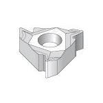
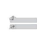
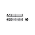
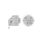
Ensure accurate and high-quality threads with Laydown Triangle (LT) threading tooling. The system is designed with a low profile for fine-pitch internal threading applications. The LT threading systems include boring bars, boring heads, toolholders, and inserts. With a wide selection of chip control inserts, you will receive superior chip management for excellent surface finishes and minimal operator intervention. The low-profile design enables unrestricted chip flow — ideal for Internal Diameter (I.D.) threads. The LT threading toolholders include an insert screw and a top clamp for easy switch outs. This comprehensive system is designed to minimize built-up edge, reduce cutting forces and precisely cut most materials.
Select Filters
Filters
Filters
View filters in
Metric
Inch
Key Filters
Workpiece Material
Workpiece Material
- P Steel (477)
- P0Low-Carbon Steels, Long Chipping C < .25%; <125 HB; <530 N/mm^2 UTS(477)
- P1Low-Carbon Steels, Short Chipping C < .25%; <125 HB; <530 N/mm^2 UTS(477)
- P2Medium and High Carbon Steels C < .25%; <220 HB; <25 HRC; >530 N/mm^2 UTS(477)
- P3Alloy Steels & Tool Steels C > .25%; <330 HB; <35 HRC; 600-850 N/mm^2 UTS(477)
- P4Alloy Steels & Tool Steels C > .25%; 350-420 HB; 35-43 HRC; 850-1400 N/mm^2 UTS(477)
- P5Ferritic, Martensitic, and PH Stainless Steels <330 HB; <35 HRC; 600-900 N/mm^2 UTS(477)
- P6High Strength Ferritic, Martensitic, and PH Stainless Steels 350-450 HB; 35-43 HRC; 900-2400 N/mm^2 UTS(477)
- M Stainless Steel (477)
- M1Austenitic Stainless Steel 130-200 HB; <600 N/mm^2 UTS(477)
- M2High Strength Austenitic Stainless and Cast Stainless Steels 150-230 HB; <25 HRC; >600 N/mm^2 UTS(477)
- M3Duplex Stainless Steel 135-275 HB; <30 HRC; 500-1200 N/mm^2 UTS(477)
- K Cast Iron (477)
- K1Gray Cast Iron 120-290 HB; <32 HRC; 125-500 N/mm^2 UTS(477)
- K2Low and Medium Strength CGI and Ductile Irons 130-260 HB; <28 HRC; <600 N/mm^2 UTS(477)
- K3High Strength Ductile and Austempered Ductile Iron 180-350 HB; <43 HRC; >600 N/mm^2 UTS(477)
- S High-Temp Alloys (477)
- S1Iron-Based, Heat-Resistant Alloys 160-260 HB; 25-48 HRC; 500-1200 N/mm^2 UTS(477)
- S2Cobalt-Based, Heat-Resistant Alloys 250-450 HB; 25-48 HRC; 1000-1450 N/mm^2 UTS(477)
- S3Nickel-Based, Heat Resistant Alloys 160-450 HB; <48 HRC; 600-1700 N/mm^2 UTS(477)
- S4Titanium and Titanium Alloys 300-400 HB; 33-43 HRC; 900-1600 N/mm^2 UTS(477)
Select First Choice
- DE (63)
- GB (41)
- SG (36)
Applications
Applications
ID Thread Turning (211)
OD Thread Turning (263)
Threading (67)
Type of Thread
Type of Thread
- 55 (101)
- 60 (154)
- ACME (75)
- API (33)
- API BUTTRESS (28)
- API RD (68)
- BSPT (56)
- BSW (144)
- M (212)
- NPT (90)
- NPTF (56)
- RD DIN 405 (78)
- STUB ACME (87)
- TR DIN 103 (104)
- UN (170)
- UNJ (89)
=
Tool Cutting Edge Angle
Tool Cutting Edge Angle
- 90.0 (120)
Tool Cutting Edge Angle MinEnter ValuetoTool Cutting Edge Angle MaxTool Cutting Edge Angle
Connection Style
Connection Style
- Bolt-On Head (1)
- Boring Bar Shank (52)
- Toolholder (67)
=
Over All Length [L]
Over All Length [L]
- 1.625 in(1)
- 2.362 in(1)
- 3.25 in(2)
- 3.346 in(2)
- 3.938 in(6)
- 4.921 in(5)
- 5.0 in(10)
- 5.906 in(13)
- 5.984 in(2)
- 6.0 in(15)
- 6.024 in(1)
- 6.063 in(2)
- 6.102 in(3)
- 6.694 in(5)
- 6.891 in(4)
- 7.0 in(9)
- 7.008 in(2)
- 7.087 in(11)
- 7.875 in(5)
- 8.0 in(1)
- 9.843 in(6)
- 10.0 in(10)
- 11.811 in(2)
- 12.0 in(2)
Over All Length [L] MinEnter ValuetoOver All Length [L] MaxOver All Length [L]
=
Over All Length [L]
Over All Length [L]
- 41.276 mm(1)
- 60.0 mm(1)
- 82.551 mm(2)
- 85.0 mm(2)
- 100.0 mm(6)
- 125.0 mm(5)
- 127.0 mm(10)
- 150.0 mm(13)
- 152.0 mm(2)
- 152.4 mm(15)
- 153.0 mm(1)
- 154.0 mm(2)
- 155.0 mm(3)
- 170.0 mm(5)
- 175.0 mm(4)
- 177.8 mm(9)
- 178.0 mm(2)
- 180.0 mm(11)
- 200.0 mm(5)
- 203.201 mm(1)
- 250.0 mm(6)
- 254.0 mm(10)
- 300.0 mm(2)
- 304.8 mm(2)
Over All Length [L] MinEnter ValuetoOver All Length [L] MaxOver All Length [L]
Corner configuration
≈
Corner Radius
Corner Radius
- 0.001 in(18)
- 0.002 in(107)
- 0.003 in(74)
- 0.004 in(30)
- 0.006 in(31)
- 0.008 in(46)
- 0.01 in(8)
- 0.011 in(50)
- 0.012 in(15)
- 0.017 in(22)
- 0.021 in(22)
- 0.027 in(3)
- 0.028 in(17)
- 0.03 in(29)
- 0.037 in(9)
- 0.038 in(1)
- 0.039 in(15)
Corner Radius MinEnter ValuetoCorner Radius MaxCorner Radius
≈
Corner Radius
Corner Radius
- 0.025 mm(18)
- 0.05 mm(107)
- 0.076 mm(74)
- 0.1 mm(30)
- 0.151 mm(31)
- 0.2 mm(46)
- 0.225 mm(8)
- 0.275 mm(50)
- 0.301 mm(15)
- 0.426 mm(22)
- 0.525 mm(22)
- 0.65 mm(3)
- 0.701 mm(17)
- 0.75 mm(29)
- 0.925 mm(9)
- 0.976 mm(1)
- 1.0 mm(15)
Corner Radius MinEnter ValuetoCorner Radius MaxCorner Radius
=
Corner Chamfer
Corner Chamfer
- 0.0 mm(366)
Corner Chamfer MinEnter ValuetoCorner Chamfer MaxCorner Chamfer
=
Corner Chamfer
Corner Chamfer
- 0.0 in(366)
Corner Chamfer MinEnter ValuetoCorner Chamfer MaxCorner Chamfer
Application
Grade Of Cutting Tool
Grade Of Cutting Tool
- KC5010 (150)
- KC5025 (417)
- KC720 (36)
- KC730 (28)
Hand Of Tool
Hand Of Tool
- L (48)
- R (72)
=
F Dimension
F Dimension
- 7.101 mm(4)
- 7.301 mm(4)
- 8.9 mm(5)
- 10.3 mm(1)
- 11.3 mm(2)
- 11.5 mm(2)
- 11.675 mm(4)
- 11.701 mm(1)
- 12.701 mm(2)
- 12.951 mm(4)
- 13.4 mm(3)
- 15.601 mm(2)
- 15.8 mm(1)
- 15.875 mm(1)
- 16.0 mm(8)
- 16.1 mm(2)
- 16.3 mm(2)
- 16.5 mm(3)
- 17.2 mm(2)
- 17.401 mm(1)
- 18.026 mm(3)
- 19.05 mm(4)
- 19.55 mm(1)
- 20.0 mm(4)
- 21.5 mm(2)
- 21.6 mm(1)
- 25.0 mm(11)
- 25.401 mm(11)
- 25.8 mm(2)
- 31.75 mm(8)
- 32.0 mm(13)
- 38.1 mm(2)
- 38.875 mm(1)
- 40.0 mm(3)
F Dimension MinEnter ValuetoF Dimension MaxF Dimension
=
F Dimension
F Dimension
- 0.28 in(4)
- 0.288 in(4)
- 0.351 in(5)
- 0.406 in(1)
- 0.445 in(2)
- 0.453 in(2)
- 0.46 in(4)
- 0.461 in(1)
- 0.5 in(2)
- 0.51 in(4)
- 0.528 in(3)
- 0.614 in(2)
- 0.622 in(1)
- 0.625 in(1)
- 0.63 in(8)
- 0.634 in(2)
- 0.642 in(2)
- 0.65 in(3)
- 0.677 in(2)
- 0.685 in(1)
- 0.71 in(3)
- 0.75 in(4)
- 0.77 in(1)
- 0.787 in(4)
- 0.846 in(2)
- 0.85 in(1)
- 0.984 in(11)
- 1.0 in(11)
- 1.016 in(2)
- 1.25 in(8)
- 1.26 in(13)
- 1.5 in(2)
- 1.532 in(1)
- 1.575 in(3)
F Dimension MinEnter ValuetoF Dimension MaxF Dimension
=
Minimum Axial Groove Diameter
Minimum Axial Groove Diameter
- 12.701 mm(4)
- 13.0 mm(4)
- 16.0 mm(2)
- 16.5 mm(3)
- 17.0 mm(1)
- 20.0 mm(5)
- 20.326 mm(4)
- 22.85 mm(4)
- 24.0 mm(3)
- 27.0 mm(2)
- 29.0 mm(5)
- 30.475 mm(3)
- 31.75 mm(3)
- 32.0 mm(3)
- 36.825 mm(1)
- 38.1 mm(1)
- 39.0 mm(2)
- 47.0 mm(2)
- 76.95 mm(1)
Minimum Axial Groove Diameter MinEnter ValuetoMinimum Axial Groove Diameter MaxMinimum Axial Groove Diameter
=
Minimum Axial Groove Diameter
Minimum Axial Groove Diameter
- 0.5 in(4)
- 0.512 in(4)
- 0.63 in(2)
- 0.65 in(3)
- 0.669 in(1)
- 0.787 in(5)
- 0.8 in(4)
- 0.9 in(4)
- 0.946 in(3)
- 1.063 in(2)
- 1.143 in(5)
- 1.2 in(3)
- 1.25 in(3)
- 1.26 in(3)
- 1.45 in(1)
- 1.5 in(1)
- 1.536 in(2)
- 1.85 in(2)
- 3.031 in(1)
Minimum Axial Groove Diameter MinEnter ValuetoMinimum Axial Groove Diameter MaxMinimum Axial Groove Diameter
=
Countersunk Angle
Countersunk Angle
- 10.0 (3)
- 14.5 (24)
- 15.0 (12)
- 27.5 (53)
- 30.0 (274)
Countersunk Angle MinEnter ValuetoCountersunk Angle MaxCountersunk Angle
Cutting Direction
Cutting Direction
- E (67)
- S (53)
Rake Angle Style
Rake Angle Style
- DOUBLE NEGATIVE (99)
- NEGATIVE-ZERO (21)
=
Maximum Bore Depth
Maximum Bore Depth
- 0.984 in(2)
- 1.0 in(2)
- 1.25 in(2)
- 1.26 in(3)
- 1.415 in(1)
- 1.5 in(2)
- 1.57 in(1)
- 1.575 in(3)
- 2.25 in(2)
- 2.362 in(2)
- 2.5 in(4)
- 2.52 in(2)
- 3.0 in(2)
- 3.15 in(4)
- 3.75 in(2)
- 3.781 in(1)
- 3.938 in(4)
- 4.5 in(2)
- 4.724 in(1)
- 5.0 in(2)
- 5.039 in(3)
- 5.906 in(1)
- 6.0 in(2)
- 6.299 in(2)
- 10.0 in(1)
Maximum Bore Depth MinEnter ValuetoMaximum Bore Depth MaxMaximum Bore Depth
=
Maximum Bore Depth
Maximum Bore Depth
- 25.0 mm(2)
- 25.401 mm(2)
- 31.75 mm(2)
- 32.0 mm(3)
- 35.95 mm(1)
- 38.1 mm(2)
- 39.875 mm(1)
- 40.0 mm(3)
- 57.151 mm(2)
- 60.0 mm(2)
- 63.5 mm(4)
- 64.0 mm(2)
- 76.2 mm(2)
- 80.0 mm(4)
- 95.25 mm(2)
- 96.0 mm(1)
- 100.0 mm(4)
- 114.301 mm(2)
- 120.0 mm(1)
- 127.0 mm(2)
- 128.0 mm(3)
- 150.0 mm(1)
- 152.4 mm(2)
- 160.0 mm(2)
- 254.0 mm(1)
Maximum Bore Depth MinEnter ValuetoMaximum Bore Depth MaxMaximum Bore Depth
Boring Bar Material
Boring Bar Material
- C (12)
- S (41)
Front-End
Clamp Style
Clamp Style
- C (58)
- M (24)
- S (17)
- Y (21)
=
Thread TPI
Thread TPI
- 4.0 (10)
- 5.0 (8)
- 6.0 (8)
- 7.0 (8)
- 8.0 (19)
- 9.0 (1)
- 10.0 (13)
- 11.0 (10)
- 11.5 (7)
- 12.0 (18)
- 14.0 (42)
- 16.0 (21)
- 18.0 (17)
- 19.0 (5)
- 20.0 (14)
- 24.0 (10)
- 27.0 (1)
- 28.0 (9)
- 32.0 (9)
- 36.0 (1)
- 40.0 (2)
- 48.0 (29)
Thread TPI MinEnter ValuetoThread TPI MaxThread TPI
=
Thread Pitch
Thread Pitch
- 0.351 mm(1)
- 0.4 mm(1)
- 0.5 mm(7)
- 0.75 mm(7)
- 0.8 mm(1)
- 1.0 mm(13)
- 1.25 mm(9)
- 1.5 mm(30)
- 1.75 mm(7)
- 2.0 mm(12)
- 2.5 mm(8)
- 3.0 mm(32)
- 3.5 mm(3)
- 4.0 mm(4)
- 4.5 mm(2)
- 5.0 mm(10)
Thread Pitch MinEnter ValuetoThread Pitch MaxThread Pitch
=
Thread Pitch
Thread Pitch
- 0.014 in(1)
- 0.016 in(1)
- 0.02 in(7)
- 0.03 in(7)
- 0.031 in(1)
- 0.039 in(13)
- 0.049 in(9)
- 0.06 in(30)
- 0.069 in(7)
- 0.079 in(12)
- 0.098 in(8)
- 0.119 in(32)
- 0.138 in(3)
- 0.157 in(4)
- 0.177 in(2)
- 0.197 in(10)
Thread Pitch MinEnter ValuetoThread Pitch MaxThread Pitch
Insert Geometry
Shape
Shape
- LT-TRIANGLE LAY DOWN THREAD 60 (366)
=
Insert IC Size
Insert IC Size
- 4.0 mm(1)
- 5.0 mm(7)
- 6.351 mm(44)
- 9.525 mm(269)
- 12.701 mm(41)
- 15.875 mm(4)
Insert IC Size MinEnter ValuetoInsert IC Size MaxInsert IC Size
=
Insert IC Size
Insert IC Size
- 0.157 in(1)
- 0.197 in(7)
- 0.25 in(44)
- 0.375 in(269)
- 0.5 in(41)
- 0.625 in(4)
Insert IC Size MinEnter ValuetoInsert IC Size MaxInsert IC Size
Insert Seat Size
Insert Seat Size
- 11 (1)
- 16 (3)
- 6 (1)
- 8 (7)
=
Cutting Edge Length
Cutting Edge Length
- 6.926 mm(1)
- 8.65 mm(7)
- 11.0 mm(1)
- 16.5 mm(3)
Cutting Edge Length MinEnter ValuetoCutting Edge Length MaxCutting Edge Length
=
Cutting Edge Length
Cutting Edge Length
- 0.273 in(1)
- 0.341 in(7)
- 0.433 in(1)
- 0.65 in(3)
Cutting Edge Length MinEnter ValuetoCutting Edge Length MaxCutting Edge Length
Back-End
Connection Type
Connection Type
- BORING BAR (52)
- BORING BAR HEAD (1)
- SQUARE SHANK (67)
=
Back-End Diameter
Back-End Diameter
- 9.525 mm(2)
- 10.0 mm(2)
- 12.701 mm(1)
- 15.875 mm(2)
- 16.0 mm(3)
- 19.05 mm(10)
- 20.0 mm(12)
- 25.0 mm(5)
- 25.401 mm(2)
- 31.75 mm(6)
- 32.0 mm(5)
- 40.0 mm(2)
- 63.5 mm(1)
Back-End Diameter MinEnter ValuetoBack-End Diameter MaxBack-End Diameter
=
Back-End Diameter
Back-End Diameter
- 0.375 in(2)
- 0.394 in(2)
- 0.5 in(1)
- 0.625 in(2)
- 0.63 in(3)
- 0.75 in(10)
- 0.787 in(12)
- 0.984 in(5)
- 1.0 in(2)
- 1.25 in(6)
- 1.26 in(5)
- 1.575 in(2)
- 2.5 in(1)
Back-End Diameter MinEnter ValuetoBack-End Diameter MaxBack-End Diameter
=
Shank Height
Shank Height
- 0.473 in(2)
- 0.5 in(2)
- 0.584 in(2)
- 0.606 in(1)
- 0.625 in(3)
- 0.63 in(4)
- 0.741 in(11)
- 0.75 in(7)
- 0.764 in(1)
- 0.787 in(7)
- 0.939 in(4)
- 0.961 in(1)
- 0.984 in(15)
- 1.0 in(13)
- 1.214 in(5)
- 1.25 in(5)
- 1.26 in(9)
- 1.53 in(2)
Shank Height MinEnter ValuetoShank Height MaxShank Height
=
Shank Height
Shank Height
- 12.0 mm(2)
- 12.701 mm(2)
- 14.826 mm(2)
- 15.4 mm(1)
- 15.875 mm(3)
- 16.0 mm(4)
- 18.825 mm(11)
- 19.05 mm(7)
- 19.401 mm(1)
- 20.0 mm(7)
- 23.826 mm(4)
- 24.401 mm(1)
- 25.0 mm(15)
- 25.401 mm(13)
- 30.826 mm(5)
- 31.75 mm(5)
- 32.0 mm(9)
- 38.825 mm(2)
Shank Height MinEnter ValuetoShank Height MaxShank Height
=
Shank Width
Shank Width
- 0.473 in(2)
- 0.5 in(2)
- 0.625 in(3)
- 0.63 in(4)
- 0.75 in(7)
- 0.787 in(8)
- 0.864 in(4)
- 0.984 in(14)
- 1.0 in(13)
- 1.141 in(5)
- 1.25 in(5)
- 1.26 in(9)
- 1.455 in(2)
Shank Width MinEnter ValuetoShank Width MaxShank Width
=
Shank Width
Shank Width
- 12.0 mm(2)
- 12.701 mm(2)
- 15.875 mm(3)
- 16.0 mm(4)
- 19.05 mm(7)
- 20.0 mm(8)
- 21.951 mm(4)
- 25.0 mm(14)
- 25.401 mm(13)
- 28.951 mm(5)
- 31.75 mm(5)
- 32.0 mm(9)
- 36.95 mm(2)
Shank Width MinEnter ValuetoShank Width MaxShank Width
No filters matching ""


