List Price
/each
Discount
Your Price
/each
Sold in pkg. of 0Adjusted to meet the minimum package size.
Minimum qty: 0Adjusted to meet the minimum quantity requirement.
In StockThis item is no longer availableLonger Delivery


 Face Milling
 Slotting: Ball Nose
 Side Milling/Shoulder Milling: Ball Nose
 Milling - Side and Face
Downloaded file will be available after import in the {{cadTool}} tool library.
| Material Number | 3101760 |
| ISO Catalog ID | KSSR050RN12CF03 |
| ANSI Catalog ID | KSSR050RN12CF03 |
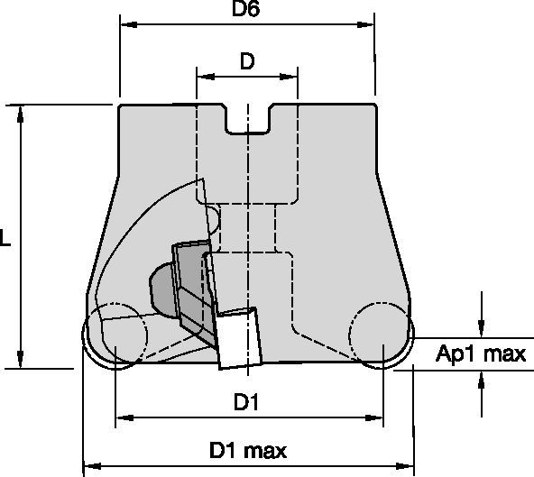
| [D1MAX] Maximum Cutting Diameter | 50 mm |
| [D1MAX] Maximum Cutting Diameter | 1.968 in |
| [D1] Effective Cutting Diameter | 37.3 mm |
| [D1] Effective Cutting Diameter | 1.468 in |
| [D] Adapter / Shank / Bore Diameter | 16 mm |
| [D] Adapter / Shank / Bore Diameter | .6299 in |
| [D6] Hub Diameter | 42 mm |
| [D6] Hub Diameter | 1.653 in |
| [L] Overall Length | 50 mm |
| [L] Overall Length | 1.968 in |
| [AP1MAX] 1st Maximum Cutting Depth | 6 mm |
| [AP1MAX] 1st Maximum Cutting Depth | .249 in |
| Number of Inserts | 3 |
| Weight Kilograms | 0.38 |
| Max RPM | 20500 |
| Gage Insert | RNGN120700 |
Face MillingSlotting: Ball NoseSide Milling/Shoulder Milling: Ball NoseMilling - Side and FaceCreate Solution to calculate Feeds and Speeds
After creating a solution just choose the Feeds & Speeds icon and our system will provide recommendations. You can customize the information by adding your machine and specifications or make adjustments using the sliders.
| Light | General | Heavy |
| Insert Geometry | Recommended Starting Feed per Tooth (Fz) in Relation to % of Radial Engagement (ae) | Insert Geometry | ||||||||||||||
| 10% | 20% | 30% | 40% | 50–100% | ||||||||||||
| ..E | 0,09 | 0,10 | 0,11 | 0,07 | 0,08 | 0,09 | 0,06 | 0,07 | 0,07 | 0,06 | 0,06 | 0,07 | 0,06 | 0,06 | 0,07 | ..E |
| ..T.. | 0,17 | 0,26 | 0,28 | 0,13 | 0,19 | 0,21 | 0,11 | 0,17 | 0,19 | 0,10 | 0,16 | 0,17 | 0,10 | 0,16 | 0,17 | ..T.. |
| Insert Geometry | Recommended Starting Feed per Tooth (Fz) in Relation to % of Radial Engagement (ae) | Insert Geometry | ||||||||||||||
| 10% | 20% | 30% | 40% | 50–100% | ||||||||||||
| ..E | 0,11 | 0,12 | 0,13 | 0,08 | 0,09 | 0,10 | 0,07 | 0,08 | 0,09 | 0,07 | 0,07 | 0,08 | 0,07 | 0,07 | 0,08 | ..E |
| ..T.. | 0,20 | 0,30 | 0,33 | 0,15 | 0,22 | 0,25 | 0,13 | 0,20 | 0,21 | 0,12 | 0,18 | 0,20 | 0,12 | 0,18 | 0,20 | ..T.. |
| Insert Geometry | Recommended Starting Feed per Tooth (Fz) in Relation to % of Radial Engagement (ae) | Insert Geometry | ||||||||||||||
| 10% | 20% | 30% | 40% | 50–100% | ||||||||||||
| ..E | 0,20 | 0,21 | 0,23 | 0,15 | 0,16 | 0,18 | 0,13 | 0,14 | 0,15 | 0,12 | 0,13 | 0,14 | 0,12 | 0,13 | 0,14 | ..E |
| ..T.. | 0,35 | 0,54 | 0,59 | 0,26 | 0,40 | 0,44 | 0,23 | 0,35 | 0,38 | 0,21 | 0,33 | 0,36 | 0,21 | 0,32 | 0,35 | ..T.. |
| Insert Geometry | Recommended Starting Feed per Tooth (Fz) in Relation to % of Radial Engagement (ae) | Insert Geometry | ||||||||||||||
| 10% | 20% | 30% | 40% | 50–100% | ||||||||||||
| ..E | 0,14 | 0,16 | 0,17 | 0,11 | 0,12 | 0,13 | 0,09 | 0,10 | 0,11 | 0,09 | 0,10 | 0,10 | 0,09 | 0,09 | 0,10 | ..E |
| ..T.. | 0,26 | 0,39 | 0,43 | 0,19 | 0,29 | 0,32 | 0,17 | 0,26 | 0,28 | 0,16 | 0,24 | 0,26 | 0,15 | 0,23 | 0,26 | ..T.. |
| Material Group | KYHS10 | KYSM10 | KYSP30 | |||||||
| P | 1 | – | – | – | – | – | – | – | – | – |
| 2 | – | – | – | – | – | – | – | – | – | |
| 3 | – | – | – | – | – | – | – | – | – | |
| 4 | – | – | – | – | – | – | – | – | – | |
| 5 | – | – | – | – | – | – | – | – | – | |
| 6 | – | – | – | – | – | – | – | – | – | |
| M | 1 | – | – | – | – | – | – | – | – | – |
| 2 | – | – | – | – | – | – | – | – | – | |
| 3 | – | – | – | – | – | – | – | – | – | |
| K | 1 | – | – | – | – | – | – | – | – | – |
| 2 | – | – | – | – | – | – | – | – | – | |
| 3 | – | – | – | – | – | – | – | – | – | |
| N | 1–2 | – | – | – | – | – | – | – | – | – |
| 3 | – | – | – | – | – | – | – | – | – | |
| S | 1 | 510 | 400 | 295 | 1065 | 870 | 675 | 805 | 660 | 510 |
| 2 | 510 | 400 | 295 | 1065 | 870 | 675 | 805 | 660 | 510 | |
| 3 | 730 | 620 | 510 | 1550 | 1260 | 970 | 1170 | 950 | 730 | |
| 4 | – | – | – | – | – | – | – | – | – | |
| H | 1 | 365 | 310 | 240 | – | – | – | – | – | – |
| Material Group | Light | General | Heavy | |||
| – | (Light geometry) | – | (Strong geometry) | |||
| – | wear |  | toughness | |||
| – | Geometry | Grade | Geometry | Grade | Geometry | Grade |
| P1–P2 | – | – | – | – | – | – |
| P3–P4 | – | – | – | – | – | – |
| P5–P6 | – | – | ..T.. | KY2100 / KYSM10 | – | – |
| M1–M2 | – | – | – | – | – | – |
| M3 | ..T.. | KY2100 / KYSM10 | ..T.. | KY2100 / KYSM10 | ..T.. | KY2100 / KYSM10 |
| K1–K2 | – | – | – | – | – | – |
| K3 | – | – | – | – | – | – |
| N1–N2 | – | – | – | – | – | – |
| N3 | – | – | – | – | – | – |
| S1–S2 | ..E | KY4300 / KYHS10 | ..T.. | KYS30 | ..T.. | KY2100 / KYSM10 |
| S3 | ..T.. | KYS30 | ..T.. | KYS30 | ..T.. | KY4300 / KYHS10 |
| S4 | – | – | – | – | – | – |
| H1 | ..E | KY4300 / KYHS10 | ..T.. | KY4300 / KYHS10 | – | – |
I have read and accepted the Terms & Conditions of use


")

ISO Catalog Number
ANSI Catalog Number
to find similar products.Please select a file to download
Models
Product data
. Please enter the desired qty for the material(s) you want to include in your promotion or Proceed Without Promotion and only your base materials will be added to the cart.
Minimum quantity should be
| SAP Material Number | ISO Catalog Number | Grade |
|---|
You are about to leave the Solution building process.
Are you sure you want to leave?