Anatomy of a Toolholder
A robust toolholder system enhances productivity, reduces tool wear, and ultimately produces superior-quality workpieces. Here’s what makes up a toolholder system.
- Shank: The shank is the base of the toolholder and is designed to fit into an adapter or directly into the machine spindle. It provides a connection between the machine and the toolholder system, transmitting power and rotational motion. It can be cylindrical or have a specific shape, depending on the type of machine and holder being used.
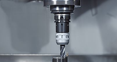
- Collet or Chuck: The collet or chuck grasps and holds the cutting tool. It can be tightened or released using a variety of ways such as drawbars, hydraulic pressure, or manual operation. They both provide excellent gripping force and versatility by being able to hold a wide range of tool shapes and sizes.
- Flange/Taper: The flange attaches the toolholder to the spindle and ensures a secure and rigid connection, minimizing vibrations and improving machining stability. Additionally, the flange may have holes or other features for mounting to the machine tool. The taper extends from the flange downwards and serves as the interface ensuring precise alignment between the toolholder and the cutting tool. Common taper designs include the CAT or CV taper,DV, HSK, KM, Morse taper, British Taper (BT) taper,VDI Tooholders, and R8.
Overall, the toolholder body is the main section of the tool holder and typically includes features such as the collet or chuck, the taper, and the flange. It may also include other features such as coolant channels, balancing cuts, or vibration-damping mechanisms.


