Product Similar To:
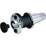
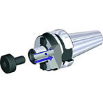
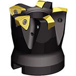
KenFeed™ 2X • Shell Mills • WOEJ09... • Inch
Shell Mills • WOEJ09...
Material Number4109596
ISO Catalog IDKF2X150W0904S050L157ANSI Catalog IDKF2X150W0904S050L157
- P Steel
- M Stainless Steel
- K Cast Iron
- S High-Temp Alloys
- H Hardened Materials
Face Milling
Helical Milling
Plunge Milling
Ramping: Blank
Slotting: Ball Nose
Side Milling/Shoulder Milling: Ball Nose
3D Profiling
Milling - Through Coolant
Milling - Side and Face
Pocketing
Sending to {{cadTool}} in progress...
Downloaded file will be available after import in the {{cadTool}} tool library.
- Overview
- Application Data
- Downloads
- Compatible Parts Machine Side
- Compatible Parts Workpiece Side
- Spare Parts
- Reviews
- Q&A
| Material Number | 4109596 |
| ISO Catalog ID | KF2X150W0904S050L157 |
| ANSI Catalog ID | KF2X150W0904S050L157 |
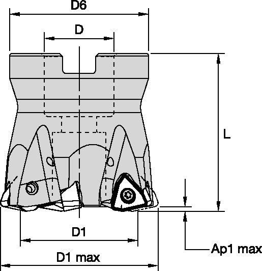
| [D1MAX] Maximum Cutting Diameter | 38.1 mm |
| [D1MAX] Maximum Cutting Diameter | 1.5 in |
| [D1] Effective Cutting Diameter | 22.06 mm |
| [D1] Effective Cutting Diameter | 0.869 in |
| [D] Adapter / Shank / Bore Diameter | 12.7 mm |
| [D] Adapter / Shank / Bore Diameter | 0.5 in |
| [D6] Hub Diameter | 36 mm |
| [D6] Hub Diameter | 1.417 in |
| [L] Overall Length | 39.9 mm |
| [L] Overall Length | 1.571 in |
| [AP1MAX] 1st Maximum Cutting Depth | 1.5 mm |
| [AP1MAX] 1st Maximum Cutting Depth | 0.059 in |
| Number of Inserts | 4 |
| Max RPM | 27400 |
| Gage Insert | WOEJ090512__ |
| Weight Pounds | 0.4 |
Workpiece Materials
- Steel
- Stainless Steel
- Cast Iron
- High-Temp Alloys
- Hardened Materials
Uses and application
Face Milling
Helical Milling
Plunge Milling
Ramping: Blank
Slotting: Ball Nose
Side Milling/Shoulder Milling: Ball Nose
3D Profiling
Milling - Through Coolant
Milling - Side and Face
Pocketing
Features and benefits
- Dramatically improves MRR using the latest milling strategies.
- Engineered to run up to 0,1 IPT.
- Ideal for pocketing, ramping, and helical interpolations. Z-plunge capabilities.
- First choice for deep cavities or from 3 x D.
Create Solution to calculate Feeds and Speeds
After creating a solution just choose the Feeds & Speeds icon and our system will provide recommendations. You can customize the information by adding your machine and specifications or make adjustments using the sliders.
Feeds
Recommended Starting Feeds [IPT]
| Insert Geometry | Recommended Starting Feed per Tooth (Fz) in Relation to % of Radial Engagement (ae) | Insert Geometry | ||||||||||||||
| 5% | 10% | 20% | 30% | 40–100% | ||||||||||||
| .S..GD | .045 | .089 | .141 | .032 | .063 | .098 | .024 | .047 | .072 | .021 | .040 | .063 | .019 | .037 | .057 | .S..GD |
| .S..HD | .045 | .109 | .168 | .032 | .077 | .116 | .024 | .057 | .085 | .021 | .049 | .074 | .019 | .045 | .067 | .S..HD |
| Light | General | Heavy |
Speeds
Recommended Starting Speeds [SFM]
| Material Group | KC522M | KC725M | KCK15 | KCPK30 | |||||||||
| P | 1 | 1300 | 1130 | 1060 | 1030 | 900 | 840 | – | – | – | 1780 | 1560 | 1450 |
| 2 | 1080 | 950 | 790 | 860 | 760 | 640 | – | – | – | 1100 | 1000 | 900 | |
| 3 | 1000 | 840 | 700 | 790 | 670 | 550 | – | – | – | 1000 | 900 | 820 | |
| 4 | 890 | 730 | 590 | 710 | 590 | 470 | – | – | – | 740 | 690 | 620 | |
| 5 | 730 | 660 | 590 | 590 | 530 | 470 | – | – | – | 1020 | 910 | 830 | |
| 6 | 650 | 490 | 400 | 520 | 400 | 310 | – | – | – | 620 | 540 | – | |
| M | 1 | 800 | 710 | 650 | 670 | 590 | 540 | – | – | – | 820 | 720 | 620 |
| 2 | 730 | 620 | 520 | 610 | 520 | 430 | – | – | – | 730 | 640 | 550 | |
| 3 | 550 | 480 | 370 | 460 | 400 | 310 | – | – | – | 570 | 520 | 460 | |
| K | 1 | 900 | 820 | 720 | – | – | – | 1660 | 1510 | 1340 | 1160 | 1050 | 940 |
| 2 | 710 | 640 | 590 | – | – | – | 1310 | 1170 | 1090 | 920 | 830 | 760 | |
| 3 | 590 | 530 | 480 | – | – | – | 1100 | 980 | 900 | 770 | 690 | 640 | |
| N | 1 | – | – | – | – | – | – | – | – | – | – | – | – |
| 2 | – | – | – | – | – | – | – | – | – | – | – | – | |
| S | 1 | 160 | 140 | 110 | 140 | 120 | 100 | – | – | – | – | – | – |
| 2 | 160 | 140 | 110 | 140 | 120 | 100 | – | – | – | – | – | – | |
| 3 | 200 | 160 | 110 | 180 | 140 | 100 | – | – | – | – | – | – | |
| 4 | 280 | 200 | 140 | 240 | 180 | 120 | – | – | – | – | – | – | |
| H | 1 | 470 | 360 | 280 | – | – | – | – | – | – | – | – | – |
| 2 | – | – | – | – | – | – | – | – | – | – | – | – | |
| 3 | – | – | – | – | – | – | – | – | – | – | – | – | |
Insert Selection
| Material Group | Light | General | Heavy | |||
| (Light geometry) | (Strong geometry) | |||||
| wear |  | toughness | ||||
| Geometry | Grade | Geometry | Grade | Geometry | Grade | |
| P1–P2 | .S..GD | KCPK30 | .S..GD | KCPM40 | .S..HD | KCPM40 |
| P3–P4 | .S..GD | KCPK30 | .S..GD | KCPM40 | .S..HD | KCPM40 |
| P5–P6 | .S..GD | KCPK30 | .S..GD | KC725M | .S..HD | KC725M |
| M1–M2 | .S..GD | KC522M | .S..GD | KC725M | .S..HD | KC725M |
| M3 | .S..GD | KCPK30 | .S..GD | KCPM40 | .S..HD | KCPM40 |
| K1–K2 | .S..HD | KCK15 | .S..HD | KCK15 | .S..HD | KCK15 |
| K3 | .S..GD | KCPK30 | .S..HD | KCK15 | .S..HD | KCPK30 |
| N1–N2 | – | – | – | – | – | – |
| N3 | – | – | – | – | – | – |
| S1–S2 | .S..GD | KC522M | .S..GD | KC725M | .S..HD | KC725M |
| S3 | .S..GD | KC725M | .S..GD | KCPM40 | .S..HD | KCPM40 |
| S4 | .S..GD | KC522M | .S..HD | KC522M | .S..HD | KC725M |
| H1 | – | – | – | – | – | – |
Application Data
| cutter type | catalog number | recommended ramping angle (for continuous ramping process) | max ramp angle when Ap max (not for continuous ramping process) | max ramp angle for 360° helical interpolation | min hole diameter (DH min) | max flat-bottom hole diameter (DH1 max) | max diameter (no flat bottom) |
| Screw-On | KF2X100W0902M12L138 | 3.5° | 5.2° | 3.1° | 1.291 | 1.35 | 2.0 |
| KF2X125W0902M16L169 | 1.9° | 2.8° | 1.7° | 1.813 | 1.87 | 2.5 | |
| KF2X125W0903M16L169 | 1.9° | 2.8° | 1.7° | 1.813 | 1.87 | 2.5 | |
| KF2X150W0903M16L169 | 1.4° | 2.1° | 1.2° | 2.310 | 2.37 | 3.0 | |
| KF2X150W0904M16L169 | 1.4° | 2.1° | 1.2° | 2.310 | 2.37 | 3.0 | |
| End Mills | KF2X100W0902C100L600 | 3.5° | 5.2° | 3.1° | 1.291 | 1.35 | 2.0 |
| KF2X100W0902C100L800 | 3.5° | 5.2° | 3.1° | 1.291 | 1.35 | 2.0 | |
| KF2X125W0903C125L600 | 1.9° | 2.8° | 1.7° | 1.813 | 1.87 | 2.5 | |
| KF2X125W0903C125L800 | 1.9° | 2.8° | 1.7° | 1.813 | 1.87 | 2.5 | |
| KF2X150W0903C125L600 | 1.4° | 2.1° | 1.2° | 2.310 | 2.37 | 3.0 | |
| KF2X150W0903C125L800 | 1.4° | 2.1° | 1.2° | 2.310 | 2.37 | 3.0 | |
| Face Mills | KF2X150W0904S050L157 | 1.4° | 2.1° | 1.2° | 2.310 | 2.37 | 3.0 |
| KF2X200W0905S075L157 | 1.0° | 1.4° | 0.8° | 3.307 | 3.37 | 4.0 | |
| KF2X200W0906S075L157 | 1.0° | 1.4° | 0.8° | 3.307 | 3.37 | 4.0 | |
| KF2X250W0906S075L175 | 0.7° | 1.1° | 0.6° | 4.305 | 4.36 | 5.0 | |
| KF2X300W0907S100L175 | 0.6° | 1.0° | 0.5° | 5.303 | 5.36 | 6.0 | |
| KF2X300W0907S125L200 | 0.6° | 1.0° | 0.5° | 5.303 | 5.36 | 6.0 |
| Rt | Wt | t |
| .110 | .312 | .045 |
Maximum Linear Ramping and Helical Interpolation from Solid
| cutter type | catalog number | recommended ramping angle (for continuous ramping process) | max ramp angle when Ap max (not for continuous ramping process) | max ramp angle for 360° helical interpolation | min hole diameter (DH min) | max flat-bottom hole diameter (DH1 max) | max diameter (no flat bottom) |
| Screw-On | KF2X2X25Z02M12WO09 | 3.6° | 5.4° | 3.1° | 26,5 | 33,7 | 50 |
| KF2X32Z03M16WO09 | 1.8° | 2.7° | 1.7° | 41,2 | 48,4 | 64 | |
| KF2X35Z03M16WO09 | 1.6° | 2.4° | 1.4° | 46,8 | 54,0 | 70 | |
| KF2X42Z04M16WO09 | 1.2° | 1.9° | 0.8° | 68,7 | 75,9 | 84 | |
| End Mills | KF2X25Z02A25WO09L140 | 3.6° | 5.4° | 3.1° | 26,5 | 33,7 | 50 |
| KF2X25Z02A25WO09L200 | 3.6° | 5.4° | 3.1° | 26,5 | 33,7 | 50 | |
| KF2X25Z02A25WO09L300 | 3.6° | 5.4° | 3.1° | 26,5 | 33,7 | 50 | |
| KF2X28Z02A25WO09L200 | 3.1° | 4.6° | 2.5° | 31,6 | 38,8 | 56 | |
| KF2X32Z03A32WO09L150 | 1.8° | 2.7° | 1.7° | 41,2 | 48,4 | 64 | |
| KF2X32Z03A32WO09L200 | 1.8° | 2.7° | 1.7° | 41,2 | 48,4 | 64 | |
| KF2X32Z03A32WO09L300 | 1.8° | 2.7° | 1.7° | 41,2 | 48,4 | 64 | |
| KF2X35Z03A32WO09L200 | 1.6° | 2.4° | 1.4° | 46,8 | 54,0 | 70 | |
| Face Mills | KF2X40Z04WO09 | 1.3° | 2.0° | 1.2° | 56,4 | 63,6 | 80 |
| KF2X50Z05WO09 | 1.0° | 1.5° | 0.8° | 76,7 | 83,9 | 100 | |
| KF2X52Z05WO09 | 1.0° | 1.4° | 0.8° | 80,7 | 87,9 | 104 | |
| KF2X63Z05S22WO09 | 0.8° | 1.2° | 0.6° | 102,7 | 109,9 | 126 | |
| KF2X63Z05WO09 | 0.8° | 1.2° | 0.6° | 102,7 | 109,9 | 126 | |
| KF2X66Z06S22WO09 | 0.7° | 1.1° | 0.5° | 108,7 | 115,9 | 132 | |
| KF2X66Z06WO09 | 0.7° | 1.1° | 0.5° | 108,7 | 115,9 | 132 | |
| KF2X80Z07WO09 | 0.6° | 0.9° | 0.4° | 136,6 | 143,8 | 160 |
Maximum Linear Ramping and Helical Interpolation from Solid
| diameter | max ramp angle | max ramp angle for 360° helical interpolation | max plunge depth | min hole diameter (DH min) | max flat-bottom hole diameter (DH1 max) | max diameter (no flat bottom) |
| 1.50 | 5.5° | 1.93° | 0.076 | 1.90 | 2.22 | 3.00 |
| 2.00 | 4.4° | 1.18° | 0.076 | 2.86 | 3.22 | 4.00 |
| 2.50 | 3.0° | 0.85° | 0.076 | 3.85 | 4.22 | 5.00 |
| 3.00 | 2.3° | 0.67° | 0.076 | 4.84 | 5.21 | 6.00 |
| 4.00 | 1.6° | 0.47° | 0.076 | 6.84 | 7.21 | 8.00 |
| 5.00 | 1.2° | 0.36° | 0.076 | 8.84 | 9.21 | 10.00 |
I have read and accepted the Terms & Conditions of use
