Produit similaire à:
KVNS™ A2™ • Arbor Mount • Inch
Slot milling cutter for multiple materials
Numéro de matériel1247790
Ref. ISO CatalogueKVNS121970DRef. ANSI CatalogueKVNS121970D
Rainurage : Fraisage de côté aux dimensions AE/AP
Sending to {{cadTool}} in progress...
Downloaded file will be available after import in the {{cadTool}} tool library.

| Numéro de matériel | 1247790 |
| Ref. ISO Catalogue | KVNS121970D |
| Ref. ANSI Catalogue | KVNS121970D |
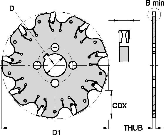
| [BM] Largeur de coupe minimale | 5.232 mm |
| [BM] Largeur de coupe minimale | 0.206 in |
| [D1] Diamètre effectif de coupe | 304.8 mm |
| [D1] Diamètre effectif de coupe | 12 in |
| [CDX] Profondeur de coupe radiale maximale | 81.026 mm |
| [CDX] Profondeur de coupe radiale maximale | 3.19 in |
| [D] Adaptateur / Queue / Diamètre d’alésage | 50.8 mm |
| [D] Adaptateur / Queue / Diamètre d’alésage | 2 in |
| [THUB] Épaisseur du moyeu | 4.4 mm |
| [THUB] Épaisseur du moyeu | 0.1732 in |
| Nombre de plaquettes | 30 |
| Plaquette étalon | OD_5197__ |
| T/Min max | 1050 |
Uses and application
Rainurage : Fraisage de côté aux dimensions AE/AP
Features and benefits
- Self-clamping insert seat with fixed stop.
- Excellent for all flat-bottom slotting and cut-off operations.
- Two drive rings required for each cutter body. They must be ordered separately, and in pairs of two.
- For cutter diameters 8" and 10" support rings are optional (instead of drive rings). Support rings also must be ordered separately, and in pairs of two.
Créez une Solution pour calculer les avances et vitesses
Après avoir créé une Solution, choisissez simplement l'icône "Avances et Vitesses" et notre système vous fournira ses recommandations. Vous pouvez les personnaliser en ajoutant votre machine et vos spécifications techniques, ou en ajustant votre demande à l'aide des curseurs.
Feeds
Avances de départ recommandées [mm]
| KVNS™ A2™ Series • Recommended Starting Feeds [mm/th] | |||||||||||||||
| Géométrie de plaquette | Avance par dent de départ recommandée (Fz) en relation avec le % de l'Engagement Radial (ae) | ||||||||||||||
| 5% | 10% | 20% | 30% | 40–100% | |||||||||||
| L | M | H | L | M | H | L | M | H | L | M | H | L | M | H | |
| .S..GD | 0,23 | 0,46 | 0,71 | 0,17 | 0,33 | 0,51 | 0,13 | 0,25 | 0,38 | 0,11 | 0,22 | 0,33 | 0,10 | 0,20 | 0,30 |
| .S..GB | 0,23 | 0,46 | 0,74 | 0,17 | 0,33 | 0,54 | 0,13 | 0,25 | 0,40 | 0,11 | 0,22 | 0,35 | 0,10 | 0,20 | 0,32 |
| L = Light Machining; M = Medium Machining; H = Heavy Machining NOTE: Use "Light Machining" values as starting feed rate. | |||||||||||||||
Recommended Starting Feeds [IPT]
| KVNS™ A2™ Series • Recommended Starting Feeds [IPT] | |||||||||||||||
| Géométrie de plaquette | Avance par dent de départ recommandée (Fz) en relation avec le % de l'Engagement Radial (ae) | ||||||||||||||
| 5% | 10% | 20% | 30% | 40–100% | |||||||||||
| L | M | H | L | M | H | L | M | H | L | M | H | L | M | H | |
| .S..GD | 0.009 | 0.017 | 0.026 | 0.007 | 0.013 | 0.019 | 0.005 | 0.009 | 0.014 | 0.004 | 0.008 | 0.012 | 0.004 | 0.008 | 0.011 |
| .S..GB | 0.009 | 0.017 | 0.028 | 0.007 | 0.013 | 0.020 | 0.005 | 0.009 | 0.015 | 0.004 | 0.008 | 0.013 | 0.004 | 0.008 | 0.012 |
| L = Light Machining; M = Medium Machining; H = Heavy Machining NOTE: Use "Light Machining" values as starting feed rate. | |||||||||||||||
Speeds
Vitesses de départ recommandées [m/mn]
| KVNS™ A2™ Series • Recommended Starting Speed [m/min] | |||||||
| nuance | KCPK30 | KMF | |||||
| Epaisseur copeau hm mm | Mini | Maxi | Mini | Maxi | |||
| Groupe Matières | Maxi | Départ | Mini | Maxi | Départ | Mini | |
| P | 1 | 455 | 395 | 370 | – | – | – |
| 2 | 280 | 255 | 230 | – | – | – | |
| 3 | 255 | 230 | 205 | – | – | – | |
| 4 | 225 | 185 | 160 | – | – | – | |
| 5 | 190 | 170 | 150 | – | – | – | |
| 6 | 160 | 135 | 110 | – | – | – | |
| M | 1 | 205 | 185 | 155 | – | – | – |
| 2 | 185 | 160 | 140 | – | – | – | |
| 3 | 145 | 130 | 115 | – | – | – | |
| K | 1 | 295 | 265 | 240 | – | – | – |
| 2 | 235 | 210 | 190 | – | – | – | |
| 3 | 195 | 175 | 160 | – | – | – | |
| N | 1 | – | – | – | 335 | 298 | 271 |
| 2 | – | – | – | 335 | 298 | 271 | |
| 3 | – | – | – | 219 | 198 | 170 | |
| S | 1 | – | – | – | 30 | 24 | 20 |
| 2 | – | – | – | 30 | 24 | 20 | |
| 3 | – | – | – | 30 | 24 | 20 | |
| 4 | 50 | 45 | 35 | 24 | 24 | 24 | |
| H | 1 | – | – | – | – | – | – |
| Recommended Starting Speed are pointing to 90° Shoulder Milling . Starting Speed for Face and Copy Milling can be Increased by 20 %. As the average chip thickness increases, speed should be decreased. Material groups P, M, K and H show recommended starting speeds for dry machining. For wet machining, reduce speed by 20%. Material groups N and S show recommended starting speeds for wet machining. Not recommended for dry machining. | |||||||
Recommended Starting Speeds [SFM]
| KVNS™ A2™ Series • Recommended Starting Speed [SFM] | |||||||
| nuance | KCPK30 | KMF | |||||
| Chip Thickness hex Inch | Mini | Maxi | Mini | Maxi | |||
| Groupe Matières | Maxi | Départ | Mini | Maxi | Départ | Mini | |
| P | 1 | 1495 | 1295 | 1215 | – | – | – |
| 2 | 920 | 835 | 755 | – | – | – | |
| 3 | 835 | 755 | 675 | – | – | – | |
| 4 | 740 | 605 | 525 | – | – | – | |
| 5 | 625 | 560 | 490 | – | – | – | |
| 6 | 525 | 445 | 360 | – | – | – | |
| M | 1 | 675 | 605 | 510 | – | – | – |
| 2 | 605 | 525 | 460 | – | – | – | |
| 3 | 475 | 425 | 375 | – | – | – | |
| K | 1 | 970 | 870 | 785 | – | – | – |
| 2 | 770 | 690 | 625 | – | – | – | |
| 3 | 640 | 575 | 525 | – | – | – | |
| N | 1 | – | – | – | 1100 | 980 | 890 |
| 2 | – | – | – | 1100 | 980 | 890 | |
| 3 | – | – | – | 720 | 650 | 560 | |
| S | 1 | – | – | – | 100 | 80 | 65 |
| 2 | – | – | – | 100 | 80 | 65 | |
| 3 | – | – | – | 100 | 80 | 65 | |
| 4 | 165 | 150 | 115 | 80 | 80 | 80 | |
| H | 1 | – | – | – | – | – | – |
| Recommended Starting Speed are pointing to 90° Shoulder Milling . Starting Speed for Face and Copy Milling can be Increased by 20 %. As the average chip thickness increases, speed should be decreased. Material groups P, M, K and H show recommended starting speeds for dry machining. For wet machining, reduce speed by 20%. Material groups N and S show recommended starting speeds for wet machining. Not recommended for dry machining. | |||||||
Guide de sélection des plaquettes
| KVNS™ A2™ Slotting Cutters • Insert Selection Guide | ||||||
| Groupe Matières | Travaux légers | Applications générales | Travaux lourds | |||
| – | (géomètrie légère) | (géomètrie solide) | ||||
| – | résistance à l’usure |  | ténacité | |||
| – | Géométrie | Nuance | Géométrie | Nuance | Géométrie | Nuance |
| P1-P2 | .S..GD | KCPK30 | .S..GD | KCPK30 | .S..GB | KCPK30 |
| P3-P4 | .S..GD | KCPK30 | .S..GD | KCPK30 | .S..GB | KCPK30 |
| P5-P6 | .S..GD | KCPK30 | .S..GB | KCPK30 | .S..GB | KCPK30 |
| M1-M2 | .S..GD | KCPK30 | .S..GD | KCPK30 | .S..GB | KCPK30 |
| M3 | .S..GD | KCPK30 | .S..GB | KCPK30 | .S..GB | KCPK30 |
| K1-K2 | .S..GD | KCPK30 | .S..GD | KCPK30 | .S..GB | KCPK30 |
| K3 | .S..GD | KCPK30 | .S..GD | KCPK30 | .S..GB | KCPK30 |
| N1-N2 | – | – | – | – | – | – |
| N3 | – | – | – | – | – | – |
| S1-S2 | – | – | – | – | – | – |
| S3 | – | – | – | – | – | – |
| S4 | – | – | – | – | – | – |
| H1 | – | – | – | – | – | – |
I have read and accepted the Terms & Conditions of use
CAD Drawings Models
Can’t find the file type you’re looking for?
Product data


