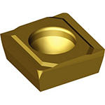
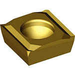
Counterboring Inserts
The CTR™ SPHX counterboring inserts are designed for high-production machining in cast iron. These square inserts are double-sided and are available in different grades. Additionally, the inserts yield high metal removal rates to reduce machine time and manufacturing costs.
- P Steel (51)
- P0Low-Carbon Steels, Long Chipping C < .25%; <125 HB; <530 N/mm^2 UTS(51)
- P1Low-Carbon Steels, Short Chipping C < .25%; <125 HB; <530 N/mm^2 UTS(51)
- P2Medium and High Carbon Steels C < .25%; <220 HB; <25 HRC; >530 N/mm^2 UTS(51)
- P3Alloy Steels & Tool Steels C > .25%; <330 HB; <35 HRC; 600-850 N/mm^2 UTS(51)
- P4Alloy Steels & Tool Steels C > .25%; 350-420 HB; 35-43 HRC; 850-1400 N/mm^2 UTS(51)
- P5Ferritic, Martensitic, and PH Stainless Steels <330 HB; <35 HRC; 600-900 N/mm^2 UTS(51)
- P6High Strength Ferritic, Martensitic, and PH Stainless Steels 350-450 HB; 35-43 HRC; 900-2400 N/mm^2 UTS(51)
- M Stainless Steel (51)
- M1Austenitic Stainless Steel 130-200 HB; <600 N/mm^2 UTS(51)
- M2High Strength Austenitic Stainless and Cast Stainless Steels 150-230 HB; <25 HRC; >600 N/mm^2 UTS(51)
- M3Duplex Stainless Steel 135-275 HB; <30 HRC; 500-1200 N/mm^2 UTS(51)
- K Cast Iron (69)
- K1Gray Cast Iron 120-290 HB; <32 HRC; 125-500 N/mm^2 UTS(69)
- K2Low and Medium Strength CGI and Ductile Irons 130-260 HB; <28 HRC; <600 N/mm^2 UTS(69)
- K3High Strength Ductile and Austempered Ductile Iron 180-350 HB; <43 HRC; >600 N/mm^2 UTS(69)
- N Non-Ferrous Materials (29)
- N1Wrought Aluminum (29)
- N2Low-Silicon Aluminum Alloys and Magnesium Alloys Si <12.2%(29)
- N3High-Silicon Aluminum Alloys Si >12.2%(25)
- N4Copper, Brass, Zinc-based on machinability index range of 70-100 (29)
- N5Nylon, Plastics, Rubbers, Phenolics, Resins, Fiberglass (29)
- N6Carbon, Graphite Composites, CFRP (29)
- N7MMC's (24)
- S High-Temp Alloys (50)
- S1Iron-Based, Heat-Resistant Alloys 160-260 HB; 25-48 HRC; 500-1200 N/mm^2 UTS(50)
- S2Cobalt-Based, Heat-Resistant Alloys 250-450 HB; 25-48 HRC; 1000-1450 N/mm^2 UTS(50)
- S3Nickel-Based, Heat Resistant Alloys 160-450 HB; <48 HRC; 600-1700 N/mm^2 UTS(50)
- S4Titanium and Titanium Alloys 300-400 HB; 33-43 HRC; 900-1600 N/mm^2 UTS(50)
- H Hardened Materials (16)
- H1Hardened Materials 44-48 HRC(16)
- H2Hardened Materials 48-55 HRC(16)
- H3Hardened Materials 56-60 HRC(16)
- H4Hardened Materials >60 HRC(16)
- Interrupted (20)
- Stable (69)
- Unstable (20)
- 0.008 in(3)
- 0.016 in(34)
- 0.024 in(4)
- 0.031 in(15)
- 0.039 in(6)
- 0.047 in(6)
- 0.063 in(5)
- 0.079 in(3)
- 0.2 mm(3)
- 0.4 mm(34)
- 0.601 mm(4)
- 0.8 mm(15)
- 1.0 mm(6)
- 1.201 mm(6)
- 1.6 mm(5)
- 2.0 mm(3)
- CS5 (1)
- KC7140 (4)
- KC7215 (32)
- KCPK10 (6)
- KCU25 (13)
- KCU40 (14)
- KM1 (6)
- 6.351 mm(13)
- 7.926 mm(16)
- 9.525 mm(20)
- 12.701 mm(18)
- 15.875 mm(9)
- 0.25 in(13)
- 0.312 in(16)
- 0.375 in(20)
- 0.5 in(18)
- 0.625 in(9)
- 6.351 mm(13)
- 7.926 mm(16)
- 9.525 mm(20)
- 12.701 mm(27)
- 0.25 in(13)
- 0.312 in(16)
- 0.375 in(20)
- 0.5 in(27)
- 20 (33)
- 21 (30)
- 22 (4)
- H (12)


