Produkt podobny do:
KDM • Frezy trzpieniowe z chwytem Weldon® • RD.X10... • Metryczne
Składane frezy trzpieniowe • RD.X10...
Nr materiału1888460
Nr katalogowy ISO20E02R120B25SRD10Nr katalogowy ANSI20E02R120B25SRD10
- P Steel
- M Stainless Steel
- K Cast Iron
- N Non-Ferrous
- S High-Temp Alloys
- H Hardened Materials
Helical Milling
Ramping: Blank
Side Milling/Shoulder Milling: Ball Nose
3D Profiling
Shank - Cylindrical Weldon
Pocketing
Sending to {{cadTool}} in progress...
Downloaded file will be available after import in the {{cadTool}} tool library.
- Podsumowanie
- Parametry skrawania
- Do pobrania
- Pasujace produkty - strona maszyny
- Pasujace produkty - strona przedmiotu obrabianego
- Części zamienne
- Opinia
- Q&A

| Nr materiału | 1888460 |
| Nr katalogowy ISO | 20E02R120B25SRD10 |
| Nr katalogowy ANSI | 20E02R120B25SRD10 |
| [D1MAX] Maximum Cutting Diameter | 20 mm |
| [D1MAX] Maximum Cutting Diameter | .7874 in |
| [D1] Effective Cutting Diameter | 10 mm |
| [D1] Effective Cutting Diameter | .3937 in |
| [D] Adapter / Shank / Bore Diameter | 25 mm |
| [D] Adapter / Shank / Bore Diameter | .9843 in |
| [L] Overall Length | 180 mm |
| [L] Overall Length | 7.086 in |
| [L1] Gage Length | 180 mm |
| [L1] Gage Length | 7.086 in |
| [L3] Usable Length | 60 mm |
| [L3] Usable Length | 2.362 in |
| [AP1MAX] 1st Maximum Cutting Depth | 5 mm |
| [AP1MAX] 1st Maximum Cutting Depth | .1969 in |
| Number of Inserts | 2 |
| Maximum Ramping Angle | 15 |
| Weight Kilograms | 0.52 |
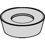
| Gage Insert | RD_X1003__ |
Materiały przedmiotu obrabianego
- Steel
- Stainless Steel
- Cast Iron
- Non-Ferrous
- High-Temp Alloys
- Hardened Materials
Zastosowania
Helical Milling
Ramping: Blank
Side Milling/Shoulder Milling: Ball Nose
3D Profiling
Shank - Cylindrical Weldon
Pocketing
Właściwości i zalety
- Odpowiednie do produkcji form i matryc.
Złóż nowe rozwiązanie aby obliczyc parametry posuwu i prędkości
Po złóżeniu rozwiązania wybierz ikonę "Posuwy i prędkości" a system pokaże rekomendowane wartości. Możesz doprecyzować wyniki dodając maszynę i jej specyfikacje lub zmień wartości początkowe Używając suwaki.
Dobór płytek
| Grupa materiałowa | Obróbka lekka | Obróbka średnia | Obróbka ciężka | |||
| – | (Lekka geometria) | – | (Zgrubna geometria) | |||
| – | odporność na zużycie |  | ciągliwość | |||
| – | Geometria | Gatunek | Geometria | Gatunek | Geometria | Gatunek |
| P1–P2 | .F..LP | KC725M | .S..HP | KC725M | .S..HP | KC725M |
| P3–P4 | .S..HP | KC522M | .S..HP | KCPK30 | .S..HP | KCPK30 |
| P5–P6 | .S..HP | KC522M | .S..HP | KCPM20 | .S..HN | KCPM20 |
| M1–M2 | .F..LP | KC725M | .S..HP | KC725M | – | – |
| M3 | .S..HP | KC522M | .S..HP | KC725M | – | – |
| K1–K2 | .S..GN | KC510M | .S..HP | KCPK30 | .S..HP | KCPK30 |
| K3 | .S..GN | KC510M | .S..HP | KCPK30 | .S..HP | KCPK30 |
| N1–N2 | .F..LP | K110M | .F..LP | K110M | .F..LP | KC510M |
| N3 | .F..LP | K110M | .F..LP | KC510M | .F..LP | KC510M |
| S1–S2 | – | – | .S..HP | KC725M | – | – |
| S3 | – | – | .S..HP | KC725M | – | – |
| S4 | – | – | .S..HP | KC725M | – | – |
| H1 | .S..HN | KC510M | .S..HN | KC510M | .S..HN | KCPM20 |
Posuwy
Przy osiowej głębokości skrawania (ap) 5,00
| Geometria płytki | Rekomendowane początkowe wartości posuwu na ząb (Fz) w relacji do % zaangażowania promieniowego (ae) | Geometria płytki | ||||||||||||||
| 10% | 20% | 30% | 40% | 50–100% | ||||||||||||
| .F..LP | 0,08 | 0,17 | 0,33 | 0,06 | 0,13 | 0,25 | 0,06 | 0,11 | 0,22 | 0,05 | 0,10 | 0,20 | 0,05 | 0,10 | 0,20 | .F..LP |
| .S..GN | 0,17 | 0,40 | 0,68 | 0,13 | 0,30 | 0,51 | 0,11 | 0,26 | 0,44 | 0,10 | 0,24 | 0,41 | 0,10 | 0,24 | 0,41 | .S..GN |
| .T..GN | 0,17 | 0,43 | 0,68 | 0,13 | 0,32 | 0,51 | 0,11 | 0,28 | 0,44 | 0,10 | 0,26 | 0,41 | 0,10 | 0,25 | 0,41 | .T..GN |
| .S..HP | 0,17 | 0,43 | 0,68 | 0,13 | 0,32 | 0,51 | 0,11 | 0,28 | 0,44 | 0,10 | 0,26 | 0,41 | 0,10 | 0,25 | 0,41 | .S..HP |
| .S..HN | 0,17 | 0,43 | 0,68 | 0,13 | 0,32 | 0,51 | 0,11 | 0,28 | 0,44 | 0,10 | 0,26 | 0,41 | 0,10 | 0,25 | 0,41 | .S..HN |
Przy osiowej głębokości skrawania (ap) 2,00
| Obróbka lekka | Obróbka średnia | Obróbka ciężka |
Przy osiowej głębokości skrawania (ap) 1,00
| Geometria płytki | Rekomendowane początkowe wartości posuwu na ząb (Fz) w relacji do % zaangażowania promieniowego (ae) | Geometria płytki | ||||||||||||||
| 10% | 20% | 30% | 40% | 50–100% | ||||||||||||
| .F..LP | 0,11 | 0,21 | 0,42 | 0,08 | 0,16 | 0,31 | 0,07 | 0,14 | 0,27 | 0,06 | 0,13 | 0,26 | 0,06 | 0,13 | 0,25 | .F..LP |
| .S..GN | 0,21 | 0,50 | 0,85 | 0,16 | 0,38 | 0,64 | 0,14 | 0,33 | 0,55 | 0,13 | 0,31 | 0,52 | 0,13 | 0,30 | 0,51 | .S..GN |
| .T..GN | 0,21 | 0,53 | 0,85 | 0,16 | 0,40 | 0,64 | 0,14 | 0,35 | 0,55 | 0,13 | 0,32 | 0,52 | 0,13 | 0,32 | 0,51 | .T..GN |
| .S..HP | 0,21 | 0,53 | 0,85 | 0,16 | 0,40 | 0,64 | 0,14 | 0,35 | 0,55 | 0,13 | 0,32 | 0,52 | 0,13 | 0,32 | 0,51 | .S..HP |
| .S..HN | 0,21 | 0,53 | 0,85 | 0,16 | 0,40 | 0,64 | 0,14 | 0,35 | 0,55 | 0,13 | 0,32 | 0,52 | 0,13 | 0,32 | 0,51 | .S..HN |
Przy osiowej głębokości skrawania (ap) 0,50
| Geometria płytki | Rekomendowane początkowe wartości posuwu na ząb (Fz) w relacji do % zaangażowania promieniowego (ae) | Geometria płytki | ||||||||||||||
| 10% | 20% | 30% | 40% | 50–100% | ||||||||||||
| .F..LP | 0,19 | 0,38 | 0,77 | 0,15 | 0,29 | 0,58 | 0,13 | 0,25 | 0,50 | 0,12 | 0,23 | 0,47 | 0,12 | 0,23 | 0,46 | .F..LP |
| .S..GN | 0,39 | 0,93 | 1,58 | 0,29 | 0,69 | 1,17 | 0,25 | 0,60 | 1,02 | 0,24 | 0,56 | 0,95 | 0,23 | 0,55 | 0,93 | .S..GN |
| .T..GN | 0,39 | 0,98 | 1,58 | 0,29 | 0,73 | 1,17 | 0,25 | 0,64 | 1,02 | 0,24 | 0,59 | 0,95 | 0,23 | 0,58 | 0,93 | .T..GN |
| .S..HP | 0,39 | 0,98 | 1,58 | 0,29 | 0,73 | 1,17 | 0,25 | 0,64 | 1,02 | 0,24 | 0,59 | 0,95 | 0,23 | 0,58 | 0,93 | .S..HP |
| .S..HN | 0,39 | 0,98 | 1,58 | 0,29 | 0,73 | 1,17 | 0,25 | 0,64 | 1,02 | 0,24 | 0,59 | 0,95 | 0,23 | 0,58 | 0,93 | .S..HN |
| Geometria płytki | Rekomendowane początkowe wartości posuwu na ząb (Fz) w relacji do % zaangażowania promieniowego (ae) | Geometria płytki | ||||||||||||||
| 10% | 20% | 30% | 40% | 50–100% | ||||||||||||
| .F..LP | 0,14 | 0,28 | 0,56 | 0,11 | 0,21 | 0,42 | 0,09 | 0,18 | 0,36 | 0,09 | 0,17 | 0,34 | 0,08 | 0,17 | 0,33 | .F..LP |
| .S..GN | 0,28 | 0,67 | 1,14 | 0,21 | 0,50 | 0,85 | 0,18 | 0,44 | 0,74 | 0,17 | 0,41 | 0,69 | 0,17 | 0,40 | 0,68 | .S..GN |
| .T..GN | 0,28 | 0,71 | 1,14 | 0,21 | 0,53 | 0,85 | 0,18 | 0,46 | 0,74 | 0,17 | 0,43 | 0,69 | 0,17 | 0,42 | 0,68 | .T..GN |
| .S..HP | 0,28 | 0,71 | 1,14 | 0,21 | 0,53 | 0,85 | 0,18 | 0,46 | 0,74 | 0,17 | 0,43 | 0,69 | 0,17 | 0,42 | 0,68 | .S..HP |
| .S..HN | 0,28 | 0,71 | 1,14 | 0,21 | 0,53 | 0,85 | 0,18 | 0,46 | 0,74 | 0,17 | 0,43 | 0,69 | 0,17 | 0,42 | 0,68 | .S..HN |
Prędkości
Zalecane wyjściowe wartości prędkości skrawania
| Grupa materiałowa | K110M | KC510M | KC522M | KC725M | KCPM20 | KCPK30 | KTPK20 | |||||||||||||||
| P | 1 | – | – | – | – | – | – | 395 | 345 | 325 | 315 | 275 | 255 | 660 | 580 | 535 | 545 | 475 | 440 | 440 | 360 | 310 |
| 2 | – | – | – | – | – | – | 330 | 290 | 240 | 260 | 230 | 195 | 410 | 370 | 330 | 335 | 305 | 275 | 270 | 225 | 190 | |
| 3 | – | – | – | – | – | – | 305 | 255 | 215 | 240 | 205 | 170 | 370 | 330 | 305 | 305 | 275 | 250 | 245 | 205 | 170 | |
| 4 | – | – | – | 295 | 240 | 200 | 270 | 225 | 180 | 215 | 180 | 145 | 275 | 255 | 230 | 225 | 210 | 190 | 185 | 160 | 130 | |
| 5 | – | – | – | – | – | – | 225 | 200 | 180 | 180 | 160 | 145 | 330 | 300 | 275 | 310 | 275 | 255 | 255 | 205 | 175 | |
| 6 | – | – | – | – | – | – | 200 | 150 | 120 | 160 | 120 | 95 | 230 | 200 | 175 | 190 | 165 | – | 150 | 125 | – | |
| M | 1 | – | – | – | – | – | – | 245 | 215 | 200 | 205 | 180 | 165 | 270 | 240 | 205 | 250 | 220 | 190 | 285 | 235 | 200 |
| 2 | – | – | – | – | – | – | 225 | 190 | 160 | 185 | 160 | 130 | 245 | 215 | 190 | 225 | 195 | 170 | 260 | 220 | 185 | |
| 3 | – | – | – | – | – | – | 170 | 145 | 115 | 140 | 120 | 95 | 195 | 175 | 150 | 175 | 160 | 140 | 195 | 160 | – | |
| K | 1 | 155 | 145 | 135 | 350 | 315 | 285 | 275 | 250 | 220 | – | – | – | 435 | 390 | 350 | 355 | 320 | 285 | 275 | 235 | 195 |
| 2 | 135 | 130 | 120 | 275 | 250 | 230 | 215 | 195 | 180 | – | – | – | 345 | 310 | 280 | 280 | 255 | 230 | 220 | 180 | 160 | |
| 3 | 120 | 105 | 95 | 235 | 205 | 190 | 180 | 160 | 145 | – | – | – | 290 | 255 | 240 | 235 | 210 | 195 | 185 | 150 | 130 | |
| N | 1–2 | 605 | 565 | 540 | 770 | 685 | 630 | – | – | – | – | – | – | – | – | – | – | – | – | – | – | – |
| 3 | 495 | 440 | 385 | – | – | – | – | – | – | – | – | – | – | – | – | – | – | – | – | – | – | |
| S | 1 | – | – | – | – | – | – | 50 | 45 | 35 | 45 | 35 | 30 | – | – | – | – | – | – | – | – | – |
| 2 | – | – | – | – | – | – | 50 | 45 | 35 | 45 | 35 | 30 | – | – | – | – | – | – | – | – | – | |
| 3 | – | – | – | – | – | – | 60 | 50 | 35 | 55 | 45 | 30 | – | – | – | – | – | – | – | – | – | |
| 4 | – | – | – | – | – | – | 85 | 60 | 45 | 75 | 55 | 35 | – | – | – | – | – | – | – | – | – | |
| H | 1 | – | – | – | 190 | 155 | 110 | 145 | 110 | 85 | – | – | – | 170 | 140 | 115 | – | – | – | – | – | – |
Recommended Starting Speeds [SFM]
| Grupa materiałowa | KC110M | KC510M | KC522M | KC725M | KCPM20 | KCPK30 | KTPK20 | |||||||||||||||
| P | 1 | – | – | – | – | – | – | 1300 | 1130 | 1060 | 1030 | 900 | 840 | 2170 | 1910 | 1760 | 1780 | 1560 | 1450 | 1440 | 1180 | 1010 |
| 2 | – | – | – | – | – | – | 1080 | 950 | 790 | 860 | 760 | 640 | 1340 | 1210 | 1090 | 1100 | 1000 | 900 | 890 | 740 | 620 | |
| 3 | – | – | – | – | – | – | 1000 | 840 | 700 | 790 | 670 | 550 | 1210 | 1090 | 1000 | 1000 | 900 | 820 | 800 | 670 | 560 | |
| 4 | – | – | – | 960 | 780 | 660 | 890 | 730 | 590 | 710 | 590 | 470 | 910 | 840 | 760 | 740 | 690 | 620 | 600 | 520 | 430 | |
| 5 | – | – | – | – | – | – | 730 | 660 | 590 | 590 | 530 | 470 | 1090 | 980 | 900 | 1020 | 910 | 830 | 830 | 680 | 580 | |
| 6 | – | – | – | – | – | – | 650 | 490 | 400 | 520 | 400 | 310 | 760 | 660 | 570 | 620 | 540 | – | 500 | 410 | – | |
| M | 1 | – | – | – | – | – | – | 800 | 710 | 650 | 670 | 590 | 540 | 880 | 790 | 680 | 820 | 720 | 620 | 940 | 770 | 650 |
| 2 | – | – | – | – | – | – | 730 | 620 | 520 | 610 | 520 | 430 | 800 | 700 | 620 | 730 | 640 | 550 | 850 | 720 | 600 | |
| 3 | – | – | – | – | – | – | 550 | 480 | 370 | 460 | 400 | 310 | 640 | 570 | 490 | 570 | 520 | 460 | 640 | 530 | – | |
| K | 1 | 510 | 480 | 450 | 1150 | 1040 | 940 | 900 | 820 | 720 | – | – | – | 1420 | 1280 | 1150 | 1160 | 1050 | 940 | 910 | 770 | 640 |
| 2 | 450 | 420 | 390 | 910 | 820 | 760 | 710 | 640 | 590 | – | – | – | 1130 | 1010 | 920 | 920 | 830 | 760 | 720 | 590 | 520 | |
| 3 | 400 | 350 | 310 | 770 | 680 | 620 | 590 | 530 | 480 | – | – | – | 950 | 840 | 780 | 770 | 690 | 640 | 600 | 500 | 420 | |
| N | 1–2 | 1980 | 1860 | 1770 | 2520 | 2240 | 2060 | – | – | – | – | – | – | – | – | – | – | – | – | – | – | – |
| 3 | 1620 | 1440 | 1260 | – | – | – | – | – | – | – | – | – | – | – | – | – | – | – | – | – | – | |
| S | 1 | – | – | – | – | – | – | 160 | 140 | 110 | 140 | 120 | 100 | – | – | – | – | – | – | – | – | – |
| 2 | – | – | – | – | – | – | 160 | 140 | 110 | 140 | 120 | 100 | – | – | – | – | – | – | – | – | – | |
| 3 | – | – | – | – | – | – | 200 | 160 | 110 | 180 | 140 | 100 | – | – | – | – | – | – | – | – | – | |
| 4 | – | – | – | – | – | – | 280 | 200 | 140 | 240 | 180 | 120 | – | – | – | – | – | – | – | – | – | |
| H | 1 | – | – | – | 630 | 510 | 360 | 470 | 360 | 280 | – | – | – | 550 | 460 | 370 | – | – | – | – | – | – |
CAD Drawings Models
Can’t find the file type you’re looking for?
Product data
I have read and accepted the Terms & Conditions of use
