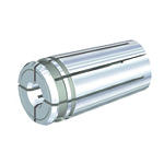
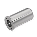
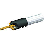
Produkt podobny do:
K105 (~5 x D) • K10/KC7210 • Chwyt A • Wiertła TF
Wiertła TF • Wysoka wydajność obróbki • Bez chłodziwa
Nr materiału1591926
Nr katalogowy ISOK105A05330Nr katalogowy ANSIDWG 1682392
Drilling
Drilling: Inclined Exit
Flood Coolant: Drilling
Shank - Cylindrical Plain ≤h6
Helix Angle: 30°
Drilling Depth: 5x
Drilling: Cross-Hole Drilling
Sending to {{cadTool}} in progress...
Downloaded file will be available after import in the {{cadTool}} tool library.

| Nr materiału | 1591926 |
| Nr katalogowy ISO | K105A05330 |
| Nr katalogowy ANSI | DWG 1682392 |
| Grade | K10 |
| [D1] Drill Diameter M | 13.5382 mm |
| [D1] Drill Diameter M | 0.533 in |
| [L] Overall Length | 124 mm |
| [L] Overall Length | 4.8819 in |
| [L3] Flute Length | 76 mm |
| [L3] Flute Length | 2.9921 in |
| [L4] Maximum Drilling Depth | 60 mm |
| [L4] Maximum Drilling Depth | 2.3622 in |
| [L5] Drill Point Length | 3.38 mm |
| [L5] Drill Point Length | 0.1331 in |
| [LS] Shank Length | 45.5 mm |
| [LS] Shank Length | 1.7913 in |
| [D] Adapter / Shank / Bore Diameter | 14.2875 mm |
| [D] Adapter / Shank / Bore Diameter | 0.5625 in |
Zastosowania
Drilling
Drilling: Inclined Exit
Flood Coolant: Drilling
Shank - Cylindrical Plain ≤h6
Helix Angle: 30°
Drilling Depth: 5x
Drilling: Cross-Hole Drilling
Gatunki

K10
Composition: Uncoated, highly wear-resistant fine-grain carbide with enhanced hot hardness properties.
Application: Best suited for dry and external flood coolant applications in aerospace materials like high-temperature resistant materials and wrought aluminum alloys. Due to its high wear-resistance, this grade is also applicable for cast iron machining at low to medium speeds.
Właściwości i zalety
- TF drills without through coolant for high metal removal rates and excellent hole quality in short chipping materials such as gray cast iron, ductile iron, and aluminum, as well as in short-hole titanium applications.
- Material-specific SC drill with three cutting edges for higher feed rates than with two-edged drills.
- Three spacious flutes for rapid chip evacuation.
- Three-margin lands deliver better hole quality and straightness than two-flute drills.
- TiAlN-coated KC7210™ grade for higher wear resistance at elevated speeds.
- Uncoated K10™ grade helps to prevent built-up edge in drilling aluminum and high-temp alloys.
Złóż nowe rozwiązanie aby obliczyc parametry posuwu i prędkości
Po złóżeniu rozwiązania wybierz ikonę "Posuwy i prędkości" a system pokaże rekomendowane wartości. Możesz doprecyzować wyniki dodając maszynę i jej specyfikacje lub zmień wartości początkowe Używając suwaki.
Parametry skrawania
Wiertła TF • Seria B105 • Gatunek K10™ • Zewnętrzne doprowadzanie chłodziwa • Wiertła o średnicy 0.1181–0.7874″ • Calowe
| Grupa materiałowa |  |  | |||||||||||
| Prędkość skrawania | Metryczne | ||||||||||||
| Zakres prędkości skrawania | Zalecana wartość prędkości posuwu w zależności od średnicy (f) | ||||||||||||
| Min. | Wartość początkowa | Maks. | 3,0 | 4,0 | 6,0 | 8,0 | 10,0 | 12,0 | 16,0 | 20,0 | |||
| K | 1 | 60 | 85 | 110 | mm/obr. | 0,11–0,20 | 0,12–0,20 | 0,16–0,28 | 0,20–0,35 | 0,22–0,42 | 0,24–0,50 | 0,28–0,61 | 0,30–0,68 |
| 2 | 70 | 70 | 90 | mm/obr. | 0,11–0,20 | 0,12–0,20 | 0,16–0,28 | 0,20–0,35 | 0,22–0,42 | 0,24–0,50 | 0,28–0,61 | 0,30–0,68 | |
| 3 | 50 | 50 | 70 | mm/obr. | 0,09–0,18 | 0,10–0,18 | 0,14–0,26 | 0,18–0,33 | 0,02–0,40 | 0,22–0,48 | 0,26–0,59 | 0,28–0,66 | |
| N | 1 | 100 | 210 | 410 | mm/obr. | 0,09–0,15 | 0,10–0,20 | 0,18–0,33 | 0,20–0,38 | 0,25–0,43 | 0,03–0,51 | 0,43–0,58 | 0,64–0,79 |
| 2 | 100 | 250 | 250 | mm/obr. | 0,10–0,19 | 0,12–0,21 | 0,18–0,33 | 0,25–0,42 | 0,30–0,50 | 0,35–0,58 | 0,44–0,74 | 0,52–0,88 | |
| 3 | 100 | 180 | 400 | mm/obr. | 0,09–0,16 | 0,10–0,20 | 0,12–0,26 | 0,16–0,36 | 0,20–0,40 | 0,24–0,45 | 0,30–0,50 | 0,34–0,60 | |
| 4 | 60 | 170 | 250 | mm/obr. | 0,08–0,15 | 0,13–0,18 | 0,18–0,33 | 0,20–0,36 | 0,23–0,38 | 0,33–0,46 | 0,38–0,48 | 0,58–0,76 | |
| S | 4 | 20 | 20 | 50 | mm/obr. | 0,03–0,05 | 0,04–0,07 | 0,07–0,09 | 0,09–0,12 | 0,11–0,15 | 0,13–0,18 | 0,17–0,24 | 0,22–0,30 |
| Grupa materiałowa |  |  | |||||||||||
| Grupa materiałowa | Prędkość skrawania | Calowe | |||||||||||
| Zakres prędkości skrawania [SFM] | Zalecana wartość prędkości posuwu w zależności od średnicy (f) | ||||||||||||
| Min. | Wartość początkowa | Maks. | 1/8 0.125 | 3/16 0.188 | 1/4 0.250 | 5/16 0.313 | 3/8 0.375 | 1/2 0.500 | 5/8 0.625 | 3/4 0.750 | |||
| K | 1 | 200 | 280 | 360 | Cali/obrót | 0.004–0.008 | 0.005–0.008 | 0.006–0.011 | 0.008–0.014 | 0.009–0.017 | 0.009–0.020 | 0.011–0.024 | 0.012–0.027 |
| 2 | 230 | 230 | 300 | Cali/obrót | 0.004–0.008 | 0.005–0.008 | 0.006–0.011 | 0.008–0.014 | 0.009–0.017 | 0.009–0.020 | 0.011–0.024 | 0.012–0.027 | |
| 3 | 160 | 160 | 230 | Cali/obrót | 0.004–0.007 | 0.004–0.007 | 0.006–0.010 | 0.007–0.013 | 0.001–0.016 | 0.009–0.019 | 0.010–0.023 | 0.011–0.026 | |
| N | 1 | 330 | 690 | 1340 | Cali/obrót | 0.004–0.006 | 0.004–0.008 | 0.007–0.013 | 0.008–0.015 | 0.010–0.017 | 0.001–0.020 | 0.017–0.023 | 0.025–0.031 |
| 2 | 330 | 820 | 820 | Cali/obrót | 0.004–0.008 | 0.005–0.008 | 0.007–0.013 | 0.010–0.017 | 0.012–0.020 | 0.014–0.023 | 0.017–0.029 | 0.021–0.035 | |
| 3 | 330 | 590 | 1310 | Cali/obrót | 0.004–0.006 | 0.004–0.008 | 0.005–0.010 | 0.006–0.014 | 0.008–0.016 | 0.009–0.018 | 0.012–0.020 | 0.013–0.024 | |
| 4 | 200 | 560 | 820 | Cali/obrót | 0.003–0.006 | 0.005–0.007 | 0.007–0.013 | 0.008–0.014 | 0.009–0.015 | 0.013–0.018 | 0.015–0.019 | 0.023–0.030 | |
| S | 4 | 70 | 70 | 160 | Cali/obrót | 0.001–0.002 | 0.002–0.003 | 0.003–0.004 | 0.004–0.005 | 0.004–0.006 | 0.005–0.007 | 0.007–0.009 | 0.009–0.012 |
 |  | ||||||||||||
| Prędkość skrawania | Metryczne | ||||||||||||
| Zakres prędkości skrawania | Zalecana wartość prędkości posuwu w zależności od średnicy (f) | ||||||||||||
| Grupa materiałowa | Min. | Wartość początkowa | Maks. | 3,0 | 4,0 | 6,0 | 8,0 | 10,0 | 12,0 | 16,0 | 20,0 | ||
| K | 1 | 60 | 85 | 110 | mm/dev | 0,11–0,20 | 0,12–0,20 | 0,16–0,28 | 0,20–0,35 | 0,22–0,42 | 0,24–0,50 | 0,28–0,61 | 0,30–0,68 |
| 2 | 70 | 72 | 90 | mm/dev | 0,11–0,20 | 0,12–0,20 | 0,16–0,28 | 0,20–0,35 | 0,22–0,42 | 0,24–0,50 | 0,28–0,61 | 0,30–0,68 | |
| 3 | 50 | 51 | 70 | mm/dev | 0,09–0,18 | 0,10–0,18 | 0,14–0,26 | 0,18–0,33 | ,020–0,40 | 0,22–0,48 | 0,26–0,59 | 0,28–0,66 | |
| N | 1 | 100 | 210 | 410 | mm/dev | 0,09–0,15 | 0,10–0,20 | 0,18–0,33 | 0,20–0,38 | 0,25–0,43 | ,033–0,51 | 0,43–0,58 | 0,64–0,79 |
| 2 | 100 | 248 | 250 | mm/dev | 0,10–0,19 | 0,12–0,21 | 0,18–0,33 | 0,25–0,42 | 0,30–0,50 | 0,35–0,58 | 0,44–0,74 | 0,52–0,88 | |
| 4 | 60 | 173 | 250 | mm/dev | 0,08–0,15 | 0,13–0,18 | 0,18–0,33 | 0,20–0,36 | 0,23–0,38 | 0,33–0,46 | 0,38–0,48 | 0,58–0,76 | |
| S | 4 | 30 | 20 | 51 | mm/dev | 0,03–0,05 | 0,04–0,07 | 0,07–0,09 | 0,09–0,12 | 0,11–0,15 | 0,13–0,18 | 0,17–0,24 | 0,22–0,30 |
| Grupa materiałowa |  |  | |||||||||||
| Grupa materiałowa | Prędkość skrawania | Calowe | |||||||||||
| Zakres prędkości skrawania [SFM] | Zalecana wartość prędkości posuwu w zależności od średnicy (f) | ||||||||||||
| Min. | Wartość początkowa | Maks. | 1/8 0.125 | 3/16 0.188 | 1/4 0.250 | 5/16 0.313 | 3/8 0.375 | 1/2 0.500 | 5/8 0.625 | 3/4 0.750 | |||
| S | 4 | 70 | 100 | 160 | Cali/obrót | – | – | 0.001–0.003 | 0.001–0.003 | 0.001–0.003 | 0.003–0.006 | 0.003–0.006 | – |
| Grupa materiałowa |  |  | |||||||||||
| Prędkość skrawania | Metryczne | ||||||||||||
| Zakres prędkości skrawania | Zalecana wartość prędkości posuwu w zależności od średnicy (f) | ||||||||||||
| Min. | Wartość początkowa | Maks. | 3,0 | 4,0 | 6,0 | 8,0 | 10,0 | 12,0 | 16,0 | 20,0 | |||
| S | 4 | 20 | 30 | 50 | mm/obr. | – | – | 0,03–0,08 | 0,03–0,08 | 0,03–0,08 | 0,08–0,15 | 0,08–0,15 | – |
 |  | ||||||||||||
| Prędkość skrawania | Metryczne | ||||||||||||
| Zakres prędkości skrawania | Zalecana wartość prędkości posuwu w zależności od średnicy (f) | ||||||||||||
| Grupa materiałowa | Min. | Wartość początkowa | Maks. | 3,0 | 4,0 | 6,0 | 8,0 | 10,0 | 12,0 | 16,0 | 20,0 | ||
| S | 4 | 20 | 30 | 50 | mm/dev | – | – | 0,03–0,08 | 0,03–0,08 | 0,03–0,08 | 0,08–0,15 | 0,08–0,15 | – |
Tolerancja
| Tolerancja • Calowe | ||
| zakres rozmiarów nominalnych | D1 tolerancja m7 | D tolerancja h6 |
| .0002/.0006 | .0000/-.0003 | |
| .0002/.0008 | .0000/-.0004 | |
| .0003/.0010 | .0000/-.0004 | |
| .0003/.0011 | .0000/-.0005 | |
| Tolerancja • Metryczne | ||
| zakres rozmiarów nominalnych | D1 tolerancja m7 | D tolerancja h6 |
| 0,004/0,016 | 0,000/-0,008 | |
| 0,006/0,021 | 0,000/-0,009 | |
| 0,007/0,025 | 0,000/-0,011 | |
| 0,008/0,029 | 0,000/-0,013 | |
I have read and accepted the Terms & Conditions of use
CAD Drawings Models
Can’t find the file type you’re looking for?
Product data
