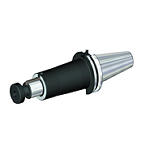
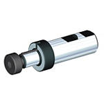
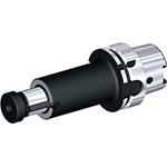
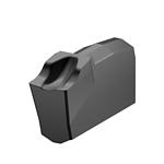
Produto semelhante ao:
KVNS™ A2™ • Arbor Mount • Inch
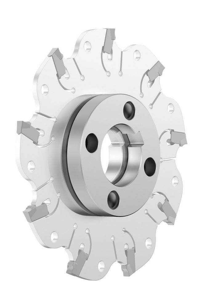
Slot milling cutter for multiple materials
Número de material1247727
ID do catálogo ISOKVNS04087ODID do catálogo ANSIKVNS04087OD
- P Steel
- M Stainless Steel
- K Cast Iron
- N Non-Ferrous
- S High-Temp Alloys
Abertura de canal: lateral com dimensões AE/AP
Sending to {{cadTool}} in progress...
Downloaded file will be available after import in the {{cadTool}} tool library.
- Visão geral
- Dados de aplicação
- Transferências
- Lado da máquina de peças compatíveis
- Lado da peça de peças compatíveis
- Peças de substituição
- Revisão
- Q&A
| Número de material | 1247727 |
| ID do catálogo ISO | KVNS04087OD |
| ID do catálogo ANSI | KVNS04087OD |
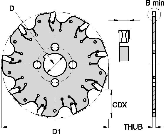
| [BM] Cutting Width Minimum | 2.22 mm |
| [BM] Cutting Width Minimum | .087 in |
| [D1] Effective Cutting Diameter | 101.6 mm |
| [D1] Effective Cutting Diameter | 4 in |
| [CDX] Radial Maximum Depth of Cut | 27 mm |
| [CDX] Radial Maximum Depth of Cut | 1.063 in |
| [D] Adapter / Shank / Bore Diameter | 25.4 mm |
| [D] Adapter / Shank / Bore Diameter | 1 in |
| [THUB] Hub Thickness | 1.8 mm |
| [THUB] Hub Thickness | .0709 in |
| Number of Inserts | 9 |
| Weight Kilograms | 0.08 |
| Gage Insert | OD_2087__ |
| Max RPM | 3200 |
Materiais das peças
- Steel
- Stainless Steel
- Cast Iron
- Non-Ferrous
- High-Temp Alloys
Usos e aplicações
Abertura de canal: lateral com dimensões AE/AP
Características e benefícios
- Self-clamping insert seat with fixed stop.
- Excellent for all flat-bottom slotting and cut-off operations.
- Two drive rings required for each cutter body. They must be ordered separately, and in pairs of two.
- For cutter diameters 8" and 10" support rings are optional (instead of drive rings). Support rings also must be ordered separately, and in pairs of two.
Criar solução para calcular avanços e velocidade
Após criar uma solução basta escolher o ícone Avanços & Velocidades e o nosso sistema irá fornecer recomendações. Pode personalizar as informações adicionando a sua máquina e especificações ou fazer ajustes utilizando os controlos deslizantes.
Seleção de insertos
Guia de seleção de insertos
| KVNS™ A2™ Slotting Cutters • Insert Selection Guide | ||||||
| Malzeme grubu | Hafif işleme | Genel amaçlı kullanım | Ağır işleme | |||
| – | (Hafif geometri) | (Sert geometri) | ||||
| – | Aşınma direnci |  | Tokluk | |||
| – | Geometri | Kalite | Geometri | Kalite | Geometri | Kalite |
| P1-P2 | .S..GD | KCPK30 | .S..GD | KCPK30 | .S..GB | KCPK30 |
| P3-P4 | .S..GD | KCPK30 | .S..GD | KCPK30 | .S..GB | KCPK30 |
| P5-P6 | .S..GD | KCPK30 | .S..GB | KCPK30 | .S..GB | KCPK30 |
| M1-M2 | .S..GD | KCPK30 | .S..GD | KCPK30 | .S..GB | KCPK30 |
| M3 | .S..GD | KCPK30 | .S..GB | KCPK30 | .S..GB | KCPK30 |
| K1-K2 | .S..GD | KCPK30 | .S..GD | KCPK30 | .S..GB | KCPK30 |
| K3 | .S..GD | KCPK30 | .S..GD | KCPK30 | .S..GB | KCPK30 |
| N1-N2 | – | – | – | – | – | – |
| N3 | – | – | – | – | – | – |
| S1-S2 | – | – | – | – | – | – |
| S3 | – | – | – | – | – | – |
| S4 | – | – | – | – | – | – |
| H1 | – | – | – | – | – | – |
Avanços
Avanços iniciais recomendados [mm]
| KVNS™ A2™ Series • Recommended Starting Feeds [mm/th] | |||||||||||||||
| Kesici uç geometrisi | Frezenin iş parçasına radyal giriş temasında (ae), diş başına başlangıç ilerleme (Fz) % oranı. | ||||||||||||||
| 5% | 10% | 20% | 30% | 40–100% | |||||||||||
| L | M | H | L | M | H | L | M | H | L | M | H | L | M | H | |
| .S..GD | 0,23 | 0,46 | 0,71 | 0,17 | 0,33 | 0,51 | 0,13 | 0,25 | 0,38 | 0,11 | 0,22 | 0,33 | 0,10 | 0,20 | 0,30 |
| .S..GB | 0,23 | 0,46 | 0,74 | 0,17 | 0,33 | 0,54 | 0,13 | 0,25 | 0,40 | 0,11 | 0,22 | 0,35 | 0,10 | 0,20 | 0,32 |
| L = Light Machining; M = Medium Machining; H = Heavy Machining NOTE: Use "Light Machining" values as starting feed rate. | |||||||||||||||
Recommended Starting Feeds [IPT]
| KVNS™ A2™ Series • Recommended Starting Feeds [IPT] | |||||||||||||||
| Kesici uç geometrisi | Frezenin iş parçasına radyal giriş temasında (ae), diş başına başlangıç ilerleme (Fz) % oranı. | ||||||||||||||
| 5% | 10% | 20% | 30% | 40–100% | |||||||||||
| L | M | H | L | M | H | L | M | H | L | M | H | L | M | H | |
| .S..GD | 0.009 | 0.017 | 0.026 | 0.007 | 0.013 | 0.019 | 0.005 | 0.009 | 0.014 | 0.004 | 0.008 | 0.012 | 0.004 | 0.008 | 0.011 |
| .S..GB | 0.009 | 0.017 | 0.028 | 0.007 | 0.013 | 0.020 | 0.005 | 0.009 | 0.015 | 0.004 | 0.008 | 0.013 | 0.004 | 0.008 | 0.012 |
| L = Light Machining; M = Medium Machining; H = Heavy Machining NOTE: Use "Light Machining" values as starting feed rate. | |||||||||||||||
Velocidades
Velocidades recomendadas iniciais [m/min]
| KVNS™ A2™ Series • Recommended Starting Speed [m/min] | |||||||
| Kalite | KCPK30 | KMF | |||||
| Talaş kalınlığı hex mm | Min. | Maks. | Min. | Maks. | |||
| Malzeme grubu | Maks. | Başlangıç | Min. | Maks. | Başlangıç | Min. | |
| P | 1 | 455 | 395 | 370 | – | – | – |
| 2 | 280 | 255 | 230 | – | – | – | |
| 3 | 255 | 230 | 205 | – | – | – | |
| 4 | 225 | 185 | 160 | – | – | – | |
| 5 | 190 | 170 | 150 | – | – | – | |
| 6 | 160 | 135 | 110 | – | – | – | |
| M | 1 | 205 | 185 | 155 | – | – | – |
| 2 | 185 | 160 | 140 | – | – | – | |
| 3 | 145 | 130 | 115 | – | – | – | |
| K | 1 | 295 | 265 | 240 | – | – | – |
| 2 | 235 | 210 | 190 | – | – | – | |
| 3 | 195 | 175 | 160 | – | – | – | |
| N | 1 | – | – | – | 335 | 298 | 271 |
| 2 | – | – | – | 335 | 298 | 271 | |
| 3 | – | – | – | 219 | 198 | 170 | |
| S | 1 | – | – | – | 30 | 24 | 20 |
| 2 | – | – | – | 30 | 24 | 20 | |
| 3 | – | – | – | 30 | 24 | 20 | |
| 4 | 50 | 45 | 35 | 24 | 24 | 24 | |
| H | 1 | – | – | – | – | – | – |
| Recommended Starting Speed are pointing to 90° Shoulder Milling . Starting Speed for Face and Copy Milling can be Increased by 20 %. As the average chip thickness increases, speed should be decreased. Material groups P, M, K and H show recommended starting speeds for dry machining. For wet machining, reduce speed by 20%. Material groups N and S show recommended starting speeds for wet machining. Not recommended for dry machining. | |||||||
Recommended Starting Speeds [SFM]
| KVNS™ A2™ Series • Recommended Starting Speed [SFM] | |||||||
| Kalite | KCPK30 | KMF | |||||
| Chip Thickness hex Inch | Min. | Maks. | Min. | Maks. | |||
| Malzeme grubu | Maks. | Başlangıç | Min. | Maks. | Başlangıç | Min. | |
| P | 1 | 1495 | 1295 | 1215 | – | – | – |
| 2 | 920 | 835 | 755 | – | – | – | |
| 3 | 835 | 755 | 675 | – | – | – | |
| 4 | 740 | 605 | 525 | – | – | – | |
| 5 | 625 | 560 | 490 | – | – | – | |
| 6 | 525 | 445 | 360 | – | – | – | |
| M | 1 | 675 | 605 | 510 | – | – | – |
| 2 | 605 | 525 | 460 | – | – | – | |
| 3 | 475 | 425 | 375 | – | – | – | |
| K | 1 | 970 | 870 | 785 | – | – | – |
| 2 | 770 | 690 | 625 | – | – | – | |
| 3 | 640 | 575 | 525 | – | – | – | |
| N | 1 | – | – | – | 1100 | 980 | 890 |
| 2 | – | – | – | 1100 | 980 | 890 | |
| 3 | – | – | – | 720 | 650 | 560 | |
| S | 1 | – | – | – | 100 | 80 | 65 |
| 2 | – | – | – | 100 | 80 | 65 | |
| 3 | – | – | – | 100 | 80 | 65 | |
| 4 | 165 | 150 | 115 | 80 | 80 | 80 | |
| H | 1 | – | – | – | – | – | – |
| Recommended Starting Speed are pointing to 90° Shoulder Milling . Starting Speed for Face and Copy Milling can be Increased by 20 %. As the average chip thickness increases, speed should be decreased. Material groups P, M, K and H show recommended starting speeds for dry machining. For wet machining, reduce speed by 20%. Material groups N and S show recommended starting speeds for wet machining. Not recommended for dry machining. | |||||||
CAD Drawings Models
Can’t find the file type you’re looking for?
Product data
I have read and accepted the Terms & Conditions of use
