Product Similar To:
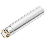
Mill 1-7™ • End Mill • Cylindrical Shank • Metric
Shoulder milling cutter for multiple materials
Material Number5190190
ISO Catalog ID12A02R018A12ED07ANSI Catalog ID12A02R018A12ED07
- P Steel
- M Stainless Steel
- K Cast Iron
- S High-Temp Alloys
- H Hardened Materials
Face Milling
Helical Milling
Ramping: Blank
Slotting: Square End
Side Milling/Shoulder Milling: Square End
Shank - Cylindrical Plain
Milling - Through Coolant
Pocketing
Sending to {{cadTool}} in progress...
Downloaded file will be available after import in the {{cadTool}} tool library.
- Overview
- Application Data
- Downloads
- Compatible Parts Machine Side
- Compatible Parts Workpiece Side
- Spare Parts
- Reviews
- Q&A

| Material Number | 5190190 |
| ISO Catalog ID | 12A02R018A12ED07 |
| ANSI Catalog ID | 12A02R018A12ED07 |
| [D1] Effective Cutting Diameter | 12 mm |
| [D1] Effective Cutting Diameter | .467 in |
| [D] Adapter / Shank / Bore Diameter | 12 mm |
| [D] Adapter / Shank / Bore Diameter | .47 in |
| [L] Overall Length | 100 mm |
| [L] Overall Length | 3.937 in |
| [L2] Head Length | 18 mm |
| [L2] Head Length | .709 in |
| [AP1MAX] 1st Maximum Cutting Depth | 6.96 mm |
| [AP1MAX] 1st Maximum Cutting Depth | .274 in |
| Number of Inserts | 2 |
| Maximum Ramping Angle | 5.18 |
| Weight Kilograms | 0.08 |
| Max RPM | 64510 |
Workpiece Materials
- Steel
- Stainless Steel
- Cast Iron
- High-Temp Alloys
- Hardened Materials
Uses and application
Face Milling
Helical Milling
Ramping: Blank
Slotting: Square End
Side Milling/Shoulder Milling: Square End
Shank - Cylindrical Plain
Milling - Through Coolant
Pocketing
Features and benefits
- Internal coolant supply.
- For ramping, slotting, plunging, facing, and true 90° walls.
Create Solution to calculate Feeds and Speeds
After creating a solution just choose the Feeds & Speeds icon and our system will provide recommendations. You can customize the information by adding your machine and specifications or make adjustments using the sliders.
Insert Selection
Insert Selection Guide
| Material Group | Light | General | Heavy | |||
| – | (Light geometry) | – | (Strong geometry) | |||
| – | wear |  | toughness | |||
| – | Geometry | Grade | Geometry | Grade | Geometry | Grade |
| P1–P2 | .S..GE | KC725M | .S..GE | KCPK30 | .S..GE | KCPM40 |
| P3–P4 | .S..GE | KC725M | .S..GE | KCPK30 | .S..GE | KCPM40 |
| P5–P6 | .S..GE | KC725M | .S..GE | KCPK30 | .S..GE | KCPM40 |
| M1–M2 | .S..GE | KC522M | .S..GE | KC725M | .S..GE | KCPM40 |
| M3 | .S..GE | KC725M | .S..GE | KCPK30 | .S..GE | KCPM40 |
| K1–K2 | .S..GE | KCPK30 | .S..GE | KCPK30 | .S..GE | KCPK30 |
| K3 | .S..GE | KCPK30 | .S..GE | KCPK30 | .S..GE | KCPK30 |
| N1–N2 | – | – | – | – | – | – |
| N3 | – | – | – | – | – | – |
| S1–S2 | .S..GE | KC522M | .S..GE | KC725M | .S..GE | KC725M |
| S3 | .S..GE | KC725M | .S..GE | KC725M | .S..GE | KCPM40 |
| S4 | .S..GE | KC522M | .S..GE | KC725M | .S..GE | KC725M |
| H1 | – | – | – | – | – | – |
Feeds
Recommended Starting Feeds [mm]
| Mill 1-7™ • Recommended Starting Feeds [mm/th] | |||||||||||||||
| Insert Geometry | Recommended Starting Feed per Tooth (Fz) in Relation to % of Radial Engagement (ae) | ||||||||||||||
| 5% | 10% | 20% | 30% | 40–100% | |||||||||||
| L | M | H | L | M | H | L | M | H | L | M | H | L | M | H | |
| .S..GE | 0,23 | 0,47 | 0,69 | 0,17 | 0,34 | 0,50 | 0,13 | 0,26 | 0,37 | 0,11 | 0,22 | 0,32 | 0,10 | 0,20 | 0,30 |
| L = Light Machining; M = Medium Machining; H = Heavy Machining NOTE: Use Light Machining values as starting feed rate. | |||||||||||||||
Recommended Starting Feeds [IPT]
| Mill 1-7™ • Recommended Starting Feeds [IPT] | |||||||||||||||
| Insert Geometry | Recommended Starting Feed per Tooth (Fz) in Relation to % of Radial Engagement (ae) | ||||||||||||||
| 5% | 10% | 20% | 30% | 40–100% | |||||||||||
| L | M | H | L | M | H | L | M | H | L | M | H | L | M | H | |
| .S..GE | 0.009 | 0.018 | 0.027 | 0.007 | 0.013 | 0.019 | 0.005 | 0.010 | 0.014 | 0.004 | 0.009 | 0.013 | 0.004 | 0.008 | 0.012 |
| L = Light Machining; M = Medium Machining; H = Heavy Machining NOTE: Use Light Machining values as starting feed rate. | |||||||||||||||
Speeds
| Mill 1-7™ • Recommended Starting Speed [m/min] | ||||||||||||||||
| Grade | KC522M | KC725M | KCPK30 | KCPM40 | KCSM30 | |||||||||||
| Chip Thickness hex mm | Min | Max | Min | Max | Min | Max | Min | Max | Min | Max | ||||||
| Material Group | Max | Start | Min | Max | Start | Min | Max | Start | Min | Max | Start | Min | Max | Start | Min | |
| P | 1 | 330 | 285 | 270 | 260 | 230 | 215 | 455 | 395 | 370 | 295 | 260 | 245 | 370 | 320 | 300 |
| 2 | 275 | 240 | 200 | 220 | 190 | 160 | 280 | 255 | 230 | 250 | 215 | 180 | 305 | 270 | 220 | |
| 3 | 255 | 215 | 175 | 200 | 170 | 140 | 255 | 230 | 205 | 230 | 195 | 160 | 285 | 240 | 195 | |
| 4 | 225 | 185 | 150 | 180 | 150 | 120 | 225 | 185 | 160 | 205 | 170 | 135 | 250 | 205 | 165 | |
| 5 | 185 | 170 | 150 | 150 | 135 | 120 | 190 | 170 | 150 | 170 | 155 | 135 | 205 | 190 | 165 | |
| 6 | 165 | 125 | 100 | 130 | 100 | 80 | 160 | 135 | 110 | 150 | 115 | 90 | 185 | 140 | 110 | |
| M | 1 | 205 | 180 | 165 | 170 | 150 | 135 | 205 | 185 | 155 | 195 | 170 | 155 | 225 | 180 | 170 |
| 2 | 185 | 160 | 130 | 155 | 130 | 110 | 185 | 160 | 140 | 175 | 150 | 125 | 205 | 160 | 135 | |
| 3 | 140 | 120 | 95 | 115 | 100 | 80 | 145 | 130 | 115 | 130 | 115 | 90 | 155 | 125 | 95 | |
| K | 1 | 230 | 205 | 185 | – | – | – | 295 | 265 | 240 | – | – | – | – | – | – |
| 2 | 180 | 160 | 150 | – | – | – | 235 | 210 | 190 | – | – | – | – | – | – | |
| 3 | 150 | 135 | 120 | – | – | – | 195 | 175 | 160 | – | – | – | – | – | – | |
| N | 1 | – | – | – | – | – | – | – | – | – | – | – | – | – | – | – |
| 2 | – | – | – | – | – | – | – | – | – | – | – | – | – | – | – | |
| 3 | – | – | – | – | – | – | – | – | – | – | – | – | – | – | – | |
| S | 1 | 40 | 35 | 25 | 35 | 30 | 25 | – | – | – | 40 | 35 | 30 | 45 | 40 | 30 |
| 2 | 40 | 35 | 25 | 35 | 30 | 25 | – | – | – | 40 | 35 | 30 | 45 | 40 | 30 | |
| 3 | 50 | 40 | 25 | 45 | 35 | 25 | – | – | – | 50 | 40 | 30 | 55 | 45 | 30 | |
| 4 | 50 | 45 | 35 | 50 | 45 | 30 | 50 | 45 | 35 | 55 | 50 | 35 | 60 | 55 | 40 | |
| H | 1 | 120 | 90 | 70 | – | – | – | – | – | – | – | – | – | 135 | 100 | 75 |
| As the average chip thickness increases, speed should be decreased. Material groups P, M, K and H show recommended starting speeds for dry machining. For wet machining, reduce speed by 20%. Material groups N and S show recommended starting speeds for wet machining. Not recommended for dry machining. | ||||||||||||||||
| Mill 1-7™ • Recommended Starting Speed [SFM] | ||||||||||||||||
| Grade | KC522M | KC725M | KCPK30 | KCPM40 | KCSM30 | |||||||||||
| Chip Thickness hex Inch | Min | Max | Min | Max | Min | Max | Min | Max | Min | Max | ||||||
| Material Group | Max | Start | Min | Max | Start | Min | Max | Start | Min | Max | Start | Min | Max | Start | Min | |
| P | 1 | 1085 | 935 | 885 | 855 | 755 | 705 | 1495 | 1295 | 1215 | 970 | 855 | 805 | 1215 | 1050 | 985 |
| 2 | 900 | 785 | 655 | 720 | 625 | 525 | 920 | 835 | 755 | 820 | 705 | 590 | 1000 | 885 | 720 | |
| 3 | 835 | 705 | 575 | 655 | 560 | 460 | 835 | 755 | 675 | 755 | 640 | 525 | 935 | 785 | 640 | |
| 4 | 740 | 605 | 490 | 590 | 490 | 395 | 740 | 605 | 525 | 675 | 560 | 445 | 820 | 675 | 540 | |
| 5 | 605 | 560 | 490 | 490 | 445 | 395 | 625 | 560 | 490 | 560 | 510 | 445 | 675 | 625 | 540 | |
| 6 | 540 | 410 | 330 | 425 | 330 | 260 | 525 | 445 | 360 | 490 | 375 | 295 | 605 | 460 | 360 | |
| M | 1 | 675 | 590 | 540 | 560 | 490 | 445 | 675 | 605 | 510 | 640 | 560 | 510 | 740 | 590 | 560 |
| 2 | 605 | 525 | 425 | 510 | 425 | 360 | 605 | 525 | 460 | 575 | 490 | 410 | 675 | 525 | 445 | |
| 3 | 460 | 395 | 310 | 375 | 330 | 260 | 475 | 425 | 375 | 425 | 375 | 295 | 510 | 410 | 310 | |
| K | 1 | 755 | 675 | 605 | – | – | – | 970 | 870 | 785 | – | – | – | – | – | – |
| 2 | 590 | 525 | 490 | – | – | – | 770 | 690 | 625 | – | – | – | – | – | – | |
| 3 | 490 | 445 | 395 | – | – | – | 640 | 575 | 525 | – | – | – | – | – | – | |
| N | 1 | – | – | – | – | – | – | – | – | – | – | – | – | – | – | – |
| 2 | – | – | – | – | – | – | – | – | – | – | – | – | – | – | – | |
| 3 | – | – | – | – | – | – | – | – | – | – | – | – | – | – | – | |
| S | 1 | 130 | 115 | 80 | 115 | 100 | 80 | – | – | – | 130 | 115 | 100 | 150 | 130 | 100 |
| 2 | 130 | 115 | 80 | 115 | 100 | 80 | – | – | – | 130 | 115 | 100 | 150 | 130 | 100 | |
| 3 | 165 | 130 | 80 | 150 | 115 | 80 | – | – | – | 165 | 130 | 100 | 180 | 150 | 100 | |
| 4 | 165 | 150 | 115 | 165 | 150 | 100 | 165 | 150 | 115 | 180 | 165 | 115 | 195 | 180 | 130 | |
| H | 1 | 395 | 295 | 230 | – | – | – | – | – | – | – | – | – | 445 | 330 | 245 |
| As the average chip thickness increases, speed should be decreased. Material groups P, M, K and H show recommended starting speeds for dry machining. For wet machining, reduce speed by 20%. Material groups N and S show recommended starting speeds for wet machining. Not recommended for dry machining. | ||||||||||||||||
Application Data
Application Examples
| Mill 1-7™ • Ramping Angles [mm] | ||||
| cutting diameter | max ramp angle to non-cutting corner tangent | DH min (min hole diameter) | DHI min (min flat-bottomed hole diameter) | max diameter (no flat bottom) |
| 12 | 5,49° | 14,62 | 21,43 | 24 |
| 16 | 2,92° | 22,52 | 28,04 | 32 |
| 20 | 2,01° | 30,51 | 36,49 | 40 |
Application Examples
| Mill 1-7™ • Ramping Angles [Inch] | ||||
| cutting diameter | max ramp angle to non-cutting corner tangent | DH min (min hole diameter) | DHI min (min flat-bottomed hole diameter) | max diameter (no flat bottom) |
| .500 | 4.56° | .628 | .886 | 1.000 |
| .625 | 2.97° | .877 | 1.095 | 1.250 |
| .750 | 2.17° | 1.126 | 1.362 | 1.500 |
I have read and accepted the Terms & Conditions of use

