Delik işleme barası sapması

Delik işleme barası sapması, kesme kuvvetleri ve beygir gücü gereksinimi

Bu hesaplamalar teorik değerleri esas alır ve sadece planlama amaçlıdır. Gerçek sonuçlar farklılık gösterecektir. Kennametal sorumluluk kabul etmemektedir.

Rockwell İş Parçası Malzemesinin Dönüşümü (İsteğe Bağlı)
Metrik
İnç

Rockwell İş Parçası Malzemesinin Dönüşümü (İsteğe Bağlı)

Brinell sertliği numarasını (HB) biliyorsanız bu adımı atlayın
Delik Barası Boyutları

Delik Barası Boyutları

inmm
Çubukta soğutucu delik kullanılmıyorsa 0
inmm
inmm
Delik Barası Malzeme Özellikleri

Delik Barası Malzeme Özellikleri

psiN/mm2
İş parçası

İş parçası

inmm
İş parçası
İş parçası"p" Değerler (hp/in.3/min) işleme koşulları için:"p" Değerler (kW/cm3/min) işleme koşulları için:
Malzeme türüTanımlamaSertliği HesaplaHassas son işlemeKaba işlemeGenelHassas son işlemeKaba işlemeGenel
Karbonlu çelikAISI 10181410.700.660.620.033220.030940.02867
Karbonlu çelikAISI 10451950.740.700.720.034580.031400.03276
Alaşımlı çelikAISI 41401940.790.740.730.037770.033220.03367
Alaşımlı çelikAISI 43402140.760.720.730.038220.033220.03367
Alaşımlı çelikAISI 41402580.850.770.790.040040.035040.03595
Alaşımlı çelikAISI 41422770.840.770.750.040500.035040.03595
Alaşımlı çelikAISI 43404851.311.001.050.059610.046870.04869
Takım çeliğiAISI H112050.780.730.760.038220.033670.03504
Paslanmaz çelikAISI 316L1470.810.730.730.038220.031850.03322
Paslanmaz çelikAISI 4102430.810.710.740.038680.033670.03413
Paslanmaz çelikAISI 17-4 PH2940.990.700.720.045510.033670.03458
Gri dökme demirSAE G30001950.530.480.470.027300.021840.02184
Sünek dökme demirASTM 65-45-121650.580.550.510.030030.023660.02366
Titanyum alaşımlıAMS Ti-6Al-4V2870.640.620.620.030940.027760.02867
Nikel alaşımıInconel 7182771.201.011.021.059610.045960.04733
Alüminyum alaşımlarıAMS 20241390.310.290.300.015470.013200.01365
hp/ln.3/min. kW/cm3/min
İşleme Koşulları

İşleme Koşulları

inmm
iprmm/rev
sfmmm/min
Takım Tezgahı Verimlilik Katsayıları
Doğrudan Kayış Tahriki.9
Arka Dişli Tahriki.75
Dişli Baş Tahriki.7-.8
Yağ - Hidrolik Tahrik.6-.9
Sonuçlarınız

Sonuçlarınız

inmm4
rpm
in.cm3/min
 
Delik Genişletme Dinamikleri

Delik Genişletme Dinamikleri

lbN
lbN
lbN
inmm
 
Beygir Gücü Hesaplama

Beygir Gücü Hesaplama

hpKW
hpKW
ft-lbsNmm
 

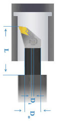
Boring Bar Deflection:

Calculating boring bar deflection, provides a means for analyzing a boring bar’s performance characteristics, prior to machining a part. Deflection can affect the surface finish or in extreme circumstances the part’s dimensional tolerances. To minimize deflection select a boring bar that offers the most rigidity with the shortest overhang.           

Boring Bar Deflection (y) Formula:

y = FL33EI

F = Cutting force [lbf or N]

Cutting force = unit of power constant x d x f x Kp x C

unit of power constant = 396,000 (Imperial) or 60,000 (Metric) 

d = DOC [inch or mm]

f = feed rate [inch per minute or mm per minute]

Kp = power constant [hp/inch3/minute or kW/mm3/minute] 

C = feed rate factor for the power constant adjustment    

L = Unsupported length (overhang) of the boring bar [inch or mm]

E = Modulus of elasticity (in tension) for the boring bar material [psi or N/mm²]

Steel Modulus of elasticity = 30,000,000 psi

Steel Modulus of elasticity = 206,843 N/mm2

Heavy Metal (Tungsten alloy) modulus of elasticity = 48,000,000 psi

Heavy Metal (Tungsten alloy) modulus of elasticity = 330,948 N/mm2 

Carbide Modulus of elasticity = 80,000,000 psi

Carbide Modulus of elasticity = 551,581 N/mm2  

Note: The stated values are specific to Kennametal boring bars.

I = Moment of inertia for the boring bar cross-sectional area

Moment of Inertia for a solid cylindrical bar = π × DOD4 ÷ 64

Moment of Inertia for a hollow cylindrical bar = π × (DOD4 - DID4) ÷ 64

To use the boring bar deflection formula you must calculate the required cutting force (F), measure the boring bar’s overhang (L), select the correct modulus of elasticity for the boring bar (E), and calculate the moment of inertia for the boring bar’s cross-sectional area (I). Once those items are input into the formula the resulting outcome will be the amount of deflection (given as a distance). 

If the resulting deflection is unacceptable; recalculate using a boring bar with a greater modulus of elasticity or a boring bar with a larger moment of inertia. 

Deflection should be minimized but balanced against what is possible, based on the intended boring operation (depth and width). 
öğesini Çözümlerim sayfanıza eklemek üzeresiniz. İlerlemek istiyor musunuz?
Select the destination where you want to move -.
Yeni Folder
    • Applied Filters:
    • Clear All

product-image
Please adjust the following properties from

ISO Katalog Numarası

ANSI Katalog Numarası

to find similar products.

The following files are available

Please select a file to download

Models

Product data

Pano bilgilerinizi görmek için oturum açmalısınız
Session expired due to inactivity, please login again
Sepete eklemeye çalıştığınız ürün(ler) () temin edilemiyor, lütfen müşteri hizmetlerine ulaşın.
ürün(ler) sepete başarıyla eklendi

. Please enter the desired qty for the material(s) you want to include in your promotion or Proceed Without Promotion and only your base materials will be added to the cart.

Minimum quantity should be

SAP Material Number ISO Katalog Numarası Kalite  

You are about to leave the Solution building process.

Are you sure you want to leave?

Standard

ALL

Material

Select a Value

Hardness

--

Hardness Scale

--

Permitted Groups :

Group

SubGroup

Hardness (HB)

Hardness (HRC)