Product Similar To:
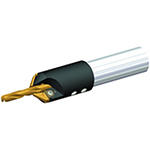
KenDrill™ 3F • 5 x D • Straight Shank • Inch
Solid Carbide Drill for Cast Iron, Non-Ferrous Materials, and Short-Hole Titanium Applications
Material Number1235611
ISO Catalog IDK105A02570ANSI Catalog IDK105A02570
- K Cast Iron
- N Non-Ferrous
- S High-Temp Alloys
Drilling
Drilling: Inclined Exit
Flood Coolant: Drilling
Shank - Cylindrical Plain ≤h6
Helix Angle: 30°
Drilling Depth: 5x
Drilling: Cross-Hole Drilling
Sending to {{cadTool}} in progress...
Downloaded file will be available after import in the {{cadTool}} tool library.

| Material Number | 1235611 |
| ISO Catalog ID | K105A02570 |
| ANSI Catalog ID | K105A02570 |
| Grade | K10 |
| [D1] Drill Diameter M | 6.5278 mm |
| [D1] Drill Diameter M | .257 in |
| [D1] Wire Size | F |
| [L] Overall Length | 91 mm |
| [L] Overall Length | 3.582 in |
| [L3] Flute Length | 50 mm |
| [L3] Flute Length | 1.968 in |
| [L4] Maximum Drilling Depth | 40.3 mm |
| [L4] Maximum Drilling Depth | 1.586 in |
| [L5] Drill Point Length | 1.63 mm |
| [L5] Drill Point Length | .0642 in |
| [LS] Shank Length | 38.5 mm |
| [LS] Shank Length | 1.515 in |
| [D] Adapter / Shank / Bore Diameter | 7.9375 mm |
| [D] Adapter / Shank / Bore Diameter | .3125 in |
Workpiece Materials
- Cast Iron
- Non-Ferrous
- High-Temp Alloys
Uses and application
Drilling
Drilling: Inclined Exit
Flood Coolant: Drilling
Shank - Cylindrical Plain ≤h6
Helix Angle: 30°
Drilling Depth: 5x
Drilling: Cross-Hole Drilling
Grades

K10
Composition: Uncoated, highly wear-resistant fine-grain carbide with enhanced hot hardness properties.
Application: Best suited for dry and external flood coolant applications in aerospace materials like high-temperature resistant materials and wrought aluminum alloys. Due to its high wear-resistance, this grade is also applicable for cast iron machining at low to medium speeds.
Features and benefits
- TF type drills without through coolant for high metal removal rates and excellent hole quality in short chipping materials such as gray cast iron, ductile iron, and aluminum, as well as in short-hole titanium applications.
- Material-specific SC drill with three cutting edges for higher feed rates than with two-edged drills.
- Three spacious flutes for rapid chip evacuation.
- Three-margin lands deliver better hole quality and straightness than two-flute drills.
- TiAlN-coated KC7210™ grade for higher wear resistance at elevated speeds.
- Uncoated K10™ grade helps to prevent built-up edge in drilling aluminum and high-temp alloys.
Create Solution to calculate Feeds and Speeds
After creating a solution just choose the Feeds & Speeds icon and our system will provide recommendations. You can customize the information by adding your machine and specifications or make adjustments using the sliders.
Tolerance
| Tolerance • Inch | ||
| nominal size range | D1 tolerance m7 | D tolerance h6 |
| .0002/.0006 | .0000/-.0003 | |
| .0002/.0008 | .0000/-.0004 | |
| .0003/.0010 | .0000/-.0004 | |
| .0003/.0011 | .0000/-.0005 | |
| Tolerance • Metric | ||
| nominal size range | D1 tolerance m7 | D tolerance h6 |
| 0,004/0,016 | 0,000/-0,008 | |
| 0,006/0,021 | 0,000/-0,009 | |
| 0,007/0,025 | 0,000/-0,011 | |
| 0,008/0,029 | 0,000/-0,013 | |
Application Data
TF Drills • B/K105 Series • Grade K10™ • Flood Coolant • Drill Diameters .1181–.7874″ • Inch
| Material |  |  | |||||||||||
| Cutting Speed | Metric | ||||||||||||
| Range | Recommended Feed Rate (f) by Diameter | ||||||||||||
| Min | Starting Value | Max | 3,0 | 4,0 | 6,0 | 8,0 | 10,0 | 12,0 | 16,0 | 20,0 | |||
| K | 1 | 60 | 85 | 110 | mm/r | 0,11–0,20 | 0,12–0,20 | 0,16–0,28 | 0,20–0,35 | 0,22–0,42 | 0,24–0,50 | 0,28–0,61 | 0,30–0,68 |
| 2 | 70 | 70 | 90 | mm/r | 0,11–0,20 | 0,12–0,20 | 0,16–0,28 | 0,20–0,35 | 0,22–0,42 | 0,24–0,50 | 0,28–0,61 | 0,30–0,68 | |
| 3 | 50 | 50 | 70 | mm/r | 0,09–0,18 | 0,10–0,18 | 0,14–0,26 | 0,18–0,33 | 0,02–0,40 | 0,22–0,48 | 0,26–0,59 | 0,28–0,66 | |
| N | 1 | 100 | 210 | 410 | mm/r | 0,09–0,15 | 0,10–0,20 | 0,18–0,33 | 0,20–0,38 | 0,25–0,43 | 0,03–0,51 | 0,43–0,58 | 0,64–0,79 |
| 2 | 100 | 250 | 250 | mm/r | 0,10–0,19 | 0,12–0,21 | 0,18–0,33 | 0,25–0,42 | 0,30–0,50 | 0,35–0,58 | 0,44–0,74 | 0,52–0,88 | |
| 3 | 100 | 180 | 400 | mm/r | 0,09–0,16 | 0,10–0,20 | 0,12–0,26 | 0,16–0,36 | 0,20–0,40 | 0,24–0,45 | 0,30–0,50 | 0,34–0,60 | |
| 4 | 60 | 170 | 250 | mm/r | 0,08–0,15 | 0,13–0,18 | 0,18–0,33 | 0,20–0,36 | 0,23–0,38 | 0,33–0,46 | 0,38–0,48 | 0,58–0,76 | |
| S | 4 | 20 | 20 | 50 | mm/r | 0,03–0,05 | 0,04–0,07 | 0,07–0,09 | 0,09–0,12 | 0,11–0,15 | 0,13–0,18 | 0,17–0,24 | 0,22–0,30 |
| Material |  |  | |||||||||||
| Material | Cutting Speed | Inch | |||||||||||
| Range | Recommended Feed Rate (f) by Diameter | ||||||||||||
| Min | Starting Value | Max | 1/8 .125 | 3/16 .188 | 1/4 .250 | 5/16 .313 | 3/8 .375 | 1/2 .500 | 5/8 .625 | 3/4 .750 | |||
| K | 1 | 200 | 280 | 360 | IPR | .004–.008 | .005–.008 | .006–.011 | .008–.014 | .009–.017 | .009–.020 | .011–.024 | .012–.027 |
| 2 | 230 | 230 | 300 | IPR | .004–.008 | .005–.008 | .006–.011 | .008–.014 | .009–.017 | .009–.020 | .011–.024 | .012–.027 | |
| 3 | 160 | 160 | 230 | IPR | .004–.007 | .004–.007 | .006–.010 | .007–.013 | .001–.016 | .009–.019 | .010–.023 | .011–.026 | |
| N | 1 | 330 | 690 | 1340 | IPR | .004–.006 | .004–.008 | .007–.013 | .008–.015 | .010–.017 | .001–.020 | .017–.023 | .025–.031 |
| 2 | 330 | 820 | 820 | IPR | .004–.008 | .005–.008 | .007–.013 | .010–.017 | .012–.020 | .014–.023 | .017–.029 | .021–.035 | |
| 3 | 330 | 590 | 1310 | IPR | .004–.006 | .004–.008 | .005–.010 | .006–.014 | .008–.016 | .009–.018 | .012–.020 | .013–.024 | |
| 4 | 200 | 560 | 820 | IPR | .003–.006 | .005–.007 | .007–.013 | .008–.014 | .009–.015 | .013–.018 | .015–.019 | .023–.030 | |
| S | 4 | 70 | 70 | 160 | IPR | .001–.002 | .002–.003 | .003–.004 | .004–.005 | .004–.006 | .005–.007 | .007–.009 | .009–.012 |
 |  | ||||||||||||
| Cutting Speed | Metric | ||||||||||||
| Range | Recommended Feed Rate (f) by Diameter | ||||||||||||
| Material | Min | Starting Value | Max | 3,0 | 4,0 | 6,0 | 8,0 | 10,0 | 12,0 | 16,0 | 20,0 | ||
| K | 1 | 60 | 85 | 110 | mm/dev | 0,11–0,20 | 0,12–0,20 | 0,16–0,28 | 0,20–0,35 | 0,22–0,42 | 0,24–0,50 | 0,28–0,61 | 0,30–0,68 |
| 2 | 70 | 72 | 90 | mm/dev | 0,11–0,20 | 0,12–0,20 | 0,16–0,28 | 0,20–0,35 | 0,22–0,42 | 0,24–0,50 | 0,28–0,61 | 0,30–0,68 | |
| 3 | 50 | 51 | 70 | mm/dev | 0,09–0,18 | 0,10–0,18 | 0,14–0,26 | 0,18–0,33 | ,020–0,40 | 0,22–0,48 | 0,26–0,59 | 0,28–0,66 | |
| N | 1 | 100 | 210 | 410 | mm/dev | 0,09–0,15 | 0,10–0,20 | 0,18–0,33 | 0,20–0,38 | 0,25–0,43 | ,033–0,51 | 0,43–0,58 | 0,64–0,79 |
| 2 | 100 | 248 | 250 | mm/dev | 0,10–0,19 | 0,12–0,21 | 0,18–0,33 | 0,25–0,42 | 0,30–0,50 | 0,35–0,58 | 0,44–0,74 | 0,52–0,88 | |
| 4 | 60 | 173 | 250 | mm/dev | 0,08–0,15 | 0,13–0,18 | 0,18–0,33 | 0,20–0,36 | 0,23–0,38 | 0,33–0,46 | 0,38–0,48 | 0,58–0,76 | |
| S | 4 | 30 | 20 | 51 | mm/dev | 0,03–0,05 | 0,04–0,07 | 0,07–0,09 | 0,09–0,12 | 0,11–0,15 | 0,13–0,18 | 0,17–0,24 | 0,22–0,30 |
| Material |  |  | |||||||||||
| Material | Cutting Speed | Inch | |||||||||||
| Range | Recommended Feed Rate (f) by Diameter | ||||||||||||
| Min | Starting Value | Max | 1/8 .125 | 3/16 .188 | 1/4 .250 | 5/16 .313 | 3/8 .375 | 1/2 .500 | 5/8 .625 | 3/4 .750 | |||
| S | 4 | 70 | 100 | 160 | IPR | – | – | .001–.003 | .001–.003 | .001–.003 | .003–.006 | .003–.006 | – |
| Material |  |  | |||||||||||
| Cutting Speed | Metric | ||||||||||||
| Range | Recommended Feed Rate (f) by Diameter | ||||||||||||
| Min | Starting Value | Max | 3,0 | 4,0 | 6,0 | 8,0 | 10,0 | 12,0 | 16,0 | 20,0 | |||
| S | 4 | 20 | 30 | 50 | mm/r | – | – | 0,03–0,08 | 0,03–0,08 | 0,03–0,08 | 0,08–0,15 | 0,08–0,15 | – |
 |  | ||||||||||||
| Cutting Speed | Metric | ||||||||||||
| Range | Recommended Feed Rate (f) by Diameter | ||||||||||||
| Material | Min | Starting Value | Max | 3,0 | 4,0 | 6,0 | 8,0 | 10,0 | 12,0 | 16,0 | 20,0 | ||
| S | 4 | 20 | 30 | 50 | mm/dev | – | – | 0,03–0,08 | 0,03–0,08 | 0,03–0,08 | 0,08–0,15 | 0,08–0,15 | – |
I have read and accepted the Terms & Conditions of use
