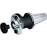
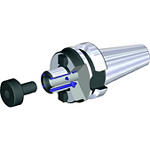
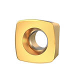
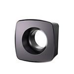
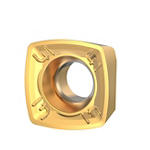
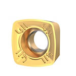
Product Similar To:
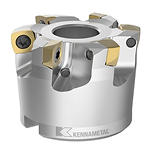
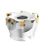
7792VXD09 Series • Shell Mill • Inch
High-Feed copy milling cutter for multiple materials.
Material Number5656731
ISO Catalog IDC7792VXD09-A1.50Z4RANSI Catalog IDC7792VXD09-A1.50Z4R
- P Steel
- M Stainless Steel
- K Cast Iron
- N Non-Ferrous
- S High-Temp Alloys
- H Hardened Materials
Spiral Circular
Slotting: Shoulder
Face Milling
Helical Milling
Ramping: Blank
Pocketing
Counter Boring
Plunge Milling: Ball Nose
Inclined Square End Mill
Sending to {{cadTool}} in progress...
Downloaded file will be available after import in the {{cadTool}} tool library.
- Overview
- Application Data
- Downloads
- Compatible Parts Machine Side
- Compatible Parts Workpiece Side
- Spare Parts
- Reviews
- Q&A
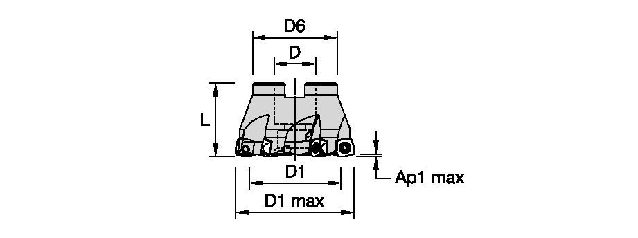
| Material Number | 5656731 |
| ISO Catalog ID | C7792VXD09-A1.50Z4R |
| ANSI Catalog ID | C7792VXD09-A1.50Z4R |
| [D1MAX] Maximum Cutting Diameter | 38.1 mm |
| [D1MAX] Maximum Cutting Diameter | 1.5 in |
| [D1] Effective Cutting Diameter | 25.11 mm |
| [D1] Effective Cutting Diameter | .989 in |
| [D] Adapter / Shank / Bore Diameter | 12.7 mm |
| [D] Adapter / Shank / Bore Diameter | .5 in |
| [D6] Hub Diameter | 36.5 mm |
| [D6] Hub Diameter | 1.437 in |
| [L] Overall Length | 32 mm |
| [L] Overall Length | 1.259 in |
| [AP1MAX] 1st Maximum Cutting Depth | 1.5 mm |
| [AP1MAX] 1st Maximum Cutting Depth | .0591 in |
| [Z] Number of Flutes | 4 |
Workpiece Materials
- Steel
- Stainless Steel
- Cast Iron
- Non-Ferrous
- High-Temp Alloys
- Hardened Materials
Uses and application
Spiral Circular
Slotting: Shoulder
Face Milling
Helical Milling
Ramping: Blank
Pocketing
Counter Boring
Plunge Milling: Ball Nose
Inclined Square End Mill
Features and benefits
- Internal coolant supply
- Positive design to support low cutting forces and applications with long overhang
Create Solution to calculate Feeds and Speeds
After creating a solution just choose the Feeds & Speeds icon and our system will provide recommendations. You can customize the information by adding your machine and specifications or make adjustments using the sliders.
Insert Selection
Insert Selection Guide • IC 09
| 7792 Series • IC09 • Insert Selection Guide | ||||||
| Material Group | Light | General | Heavy | |||
| – | (Light geometry) | – | (Strong geometry) | |||
| – | wear |  | toughness | |||
| – | Geometry | Grade | Geometry | Grade | Geometry | Grade |
| P1-P2 | ...M41 | KCPM40 | …M41 | KCPM40 | …GP | KCPM40 |
| P3-P4 | ...M41 | KCPM40 | …D411 | SP6519 | …D41 | KCPM40 |
| P5-P6 | ...M41 | KCPM40 | ...D41 | SP6519 | ...D41 | X500 |
| M1-M2 | ...M41 | KCSM40 | ...D411 | KCSM40 | ...D41 | KCSM40 |
| M3 | ...M41 | KCSM40 | ...D41 | KCSM40 | ...D41 | KCSM40 |
| K1-K2 | …M | KCK20B | …M | KCK20B | …D | KCPK30 |
| K3 | …M | KCK20B | …M | KCK20B | …D | KCPK30 |
| N1-N2 | – | – | – | – | – | – |
| N3 | – | – | – | – | – | – |
| S1-S2 | ...M41 | X500 | ...D411 | KCSM40 | ...D41 | KCSM40 |
| S3 | ...M41 | X500 | ...D411 | KCSM40 | ...D41 | KCSM40 |
| S4 | ...M41 | X500 | ...D411 | KCSM40 | ...D41 | KCSM40 |
| H1 | …M | KCKP10 | …M | KCKP10 | …D | KCPM40 |
Feeds
| 7792 Series • IC09 • Recommended Starting Feeds [mm/th] | |||||||
| Insert Geometry | Recommended Starting Feed per Tooth (Fz) in Relation to % of Radial Engagement (ae) | ||||||
| DOC | 30% | 40–100% | |||||
| (mm) | L | M | H | L | M | H | |
| .S..D | 1,5 | 0,25 | 0,55 | 0,88 | 0,23 | 0,50 | 0,80 |
| .S..D | 1,1 | 0,30 | 0,64 | 1,02 | 0,27 | 0,59 | 0,93 |
| .S..D | 0,9 | 0,33 | 0,71 | 1,12 | 0,30 | 0,64 | 1,03 |
| .E..D41 | 1,5 | 0,18 | 0,50 | 0,75 | 0,16 | 0,46 | 0,69 |
| .E..D41 | 1,1 | 0,21 | 0,58 | 0,87 | 0,19 | 0,53 | 0,80 |
| .E..D41 | 0,9 | 0,23 | 0,64 | 0,96 | 0,21 | 0,59 | 0,88 |
| .E..D411 | 1,5 | 0,18 | 0,50 | 0,75 | 0,16 | 0,46 | 0,69 |
| .E..D411 | 1,1 | 0,21 | 0,58 | 0,87 | 0,19 | 0,53 | 0,80 |
| .E..D411 | 0,9 | 0,23 | 0,64 | 0,96 | 0,21 | 0,59 | 0,88 |
| .S..GP | 1,5 | 0,25 | 0,55 | 0,89 | 0,23 | 0,51 | 0,81 |
| .S..GP | 1,1 | 0,30 | 0,64 | 1,03 | 0,27 | 0,59 | 0,94 |
| .S..GP | 0,9 | 0,33 | 0,71 | 1,14 | 0,30 | 0,65 | 1,04 |
| .S...M | 1,5 | 0,25 | 0,55 | 0,88 | 0,23 | 0,50 | 0,80 |
| .S...M | 1,1 | 0,30 | 0,64 | 1,02 | 0,27 | 0,59 | 0,93 |
| .S..M | 0,9 | 0,33 | 0,71 | 1,12 | 0,30 | 0,64 | 1,03 |
| .E..M41 | 1,5 | 0,18 | 0,50 | 0,75 | 0,16 | 0,46 | 0,69 |
| .E...M41 | 1,1 | 0,21 | 0,58 | 0,87 | 0,19 | 0,53 | 0,80 |
| .E..M41 | 0,9 | 0,23 | 0,64 | 0,96 | 0,21 | 0,59 | 0,88 |
| L = Light Machining; M = Medium Machining; H = Heavy Machining NOTE: Use Light Machining values as starting feed rate. | |||||||
| 7792 Series • IC09 • Recommended Starting Feeds [IPT] | |||||||
| Insert Geometry | Recommended Starting Feed per Tooth (Fz) in Relation to % of Radial Engagement (ae) | ||||||
| DOC | 30% | 40–100% | |||||
| (Inch) | L | M | H | L | M | H | |
| .S..D | 0.06 | 0.010 | 0.022 | 0.035 | 0.009 | 0.020 | 0.032 |
| .S..D | 0.04 | 0.012 | 0.027 | 0.042 | 0.011 | 0.024 | 0.039 |
| .S..D | 0.03 | 0.014 | 0.031 | 0.049 | 0.013 | 0.028 | 0.044 |
| .E..D41 | 0.06 | 0.007 | 0.020 | 0.030 | 0.006 | 0.018 | 0.027 |
| .E..D41 | 0.04 | 0.009 | 0.024 | 0.036 | 0.008 | 0.022 | 0.033 |
| .E..D41 | 0.03 | 0.010 | 0.028 | 0.042 | 0.009 | 0.025 | 0.038 |
| .E..D411 | 0.06 | 0.007 | 0.020 | 0.030 | 0.006 | 0.018 | 0.027 |
| .E..D411 | 0.04 | 0.009 | 0.024 | 0.036 | 0.008 | 0.022 | 0.033 |
| .E..D411 | 0.03 | 0.010 | 0.028 | 0.042 | 0.009 | 0.025 | 0.038 |
| .S..GP | 0.06 | 0.010 | 0.022 | 0.035 | 0.009 | 0.020 | 0.032 |
| .S..GP | 0.04 | 0.012 | 0.026 | 0.042 | 0.011 | 0.024 | 0.038 |
| .S..GP | 0.03 | 0.014 | 0.030 | 0.048 | 0.013 | 0.028 | 0.044 |
| .S...M | 0.06 | 0.010 | 0.022 | 0.035 | 0.009 | 0.020 | 0.032 |
| .S...M | 0.04 | 0.012 | 0.027 | 0.042 | 0.011 | 0.024 | 0.039 |
| .S..M | 0.03 | 0.014 | 0.031 | 0.049 | 0.013 | 0.028 | 0.044 |
| .E..M41 | 0.06 | 0.007 | 0.020 | 0.030 | 0.006 | 0.018 | 0.027 |
| .E...M41 | 0.04 | 0.009 | 0.024 | 0.036 | 0.008 | 0.022 | 0.033 |
| .E..M41 | 0.03 | 0.010 | 0.028 | 0.042 | 0.009 | 0.025 | 0.038 |
| L = Light Machining; M = Medium Machining; H = Heavy Machining NOTE: Use Light Machining values as starting feed rate. | |||||||
| Light | General | Heavy |
| 7792 Series • IC09 • Recommended Starting Feeds for Plunging [mm/th] | ||||
| Insert Geometry |  | Programmed Feed per Tooth (fz) | ||
| L | M | H | ||
| .S..D | 0,10 | 0,22 | 0,35 | |
| .E..D41 | 0,07 | 0,20 | 0,30 | |
| .E..D411 | 0,07 | 0,20 | 0,30 | |
| .S..GP | 0,10 | 0,22 | 0,35 | |
| .S..M | 0,10 | 0,22 | 0,35 | |
| .E..M41 | 0,07 | 0,20 | 0,30 | |
| L = Light Machining; M = Medium Machining; H = Heavy Machining NOTE: Use Light Machining values as starting feed rate. | ||||
| Light | General | Heavy |
| 7792 Series • IC09 • Recommended Starting Feeds for Plunging [IPT] | ||||
| Insert Geometry |  | Programmed Feed per Tooth (fz) | ||
| L | M | H | ||
| .S..D | 0.004 | 0.009 | 0.014 | |
| .E..D41 | 0.003 | 0.008 | 0.012 | |
| .E..D411 | 0.003 | 0.008 | 0.012 | |
| .S..GP | 0.004 | 0.009 | 0.014 | |
| .S..M | 0.004 | 0.009 | 0.014 | |
| .E..M41 | 0.003 | 0.008 | 0.012 | |
| L = Light Machining; M = Medium Machining; H = Heavy Machining NOTE: Use Light Machining values as starting feed rate. | ||||
Speeds
| 7792 Series IC09 • Recommended Starting Speed [m/min] | ||||||||||||||||||||||||||||||||||
| Grade | KC522M | KC725M | KCK15 | KCPK30 | KCKP10 | KCK20B | KCPM40 | KCSM40 | SP6519 | X400 | X500 | |||||||||||||||||||||||
| Chip Thickness hex mm | Min | Max | Min | Max | Min | Max | Min | Max | Min | Max | Min | Max | Min | Max | Min | Max | Min | Max | Min | Max | Min | Max | ||||||||||||
| Material Group | Max | Start | Min | Max | Start | Min | Max | Start | Min | Max | Start | Min | Max | Start | Min | Max | Start | Min | Max | Start | Min | Max | Start | Min | Max | Start | Min | Max | Start | Min | Max | Start | Min | |
| P | 1 | 330 | 285 | 270 | 260 | 230 | 215 | – | – | – | 455 | 395 | 370 | 300 | 295 | 260 | – | – | – | 295 | 260 | 245 | 350 | 320 | 300 | 295 | 215 | 130 | 260 | 190 | 120 | 270 | 200 | 130 |
| 2 | 275 | 240 | 200 | 220 | 190 | 160 | – | – | – | 280 | 255 | 230 | 310 | 275 | 240 | – | – | – | 250 | 215 | 180 | 300 | 270 | 220 | 260 | 190 | 115 | 230 | 170 | 105 | 240 | 280 | 115 | |
| 3 | 255 | 215 | 175 | 200 | 170 | 140 | – | – | – | 255 | 230 | 205 | 275 | 240 | 205 | – | – | – | 230 | 195 | 160 | 280 | 240 | 195 | 230 | 165 | 100 | 200 | 150 | 95 | 210 | 155 | 100 | |
| 4 | 225 | 185 | 150 | 180 | 150 | 120 | – | – | – | 225 | 185 | 160 | 240 | 205 | 160 | – | – | – | 205 | 170 | 135 | 240 | 205 | 165 | 175 | 125 | 75 | 150 | 110 | 70 | 160 | 120 | 75 | |
| 5 | 185 | 170 | 150 | 150 | 135 | 120 | – | – | – | 190 | 170 | 150 | 205 | 160 | 125 | – | – | – | 170 | 155 | 135 | 200 | 180 | 160 | 140 | 105 | 70 | – | – | – | 130 | 100 | 70 | |
| 6 | 165 | 125 | 100 | 130 | 100 | 80 | – | – | – | 160 | 135 | 110 | 160 | 125 | 110 | – | – | – | 150 | 115 | 90 | 180 | 140 | 100 | 120 | 85 | 50 | – | – | – | 110 | 80 | 50 | |
| M | 1 | 205 | 180 | 165 | 170 | 150 | 135 | – | – | – | 205 | 185 | 155 | – | – | – | – | – | – | 195 | 170 | 155 | 260 | 210 | 185 | 270 | 195 | 115 | – | – | – | 250 | 185 | 115 |
| 2 | 185 | 160 | 130 | 155 | 130 | 110 | – | – | – | 185 | 160 | 140 | – | – | – | – | – | – | 175 | 150 | 125 | 235 | 180 | 145 | 235 | 170 | 105 | – | – | – | 220 | 160 | 100 | |
| 3 | 140 | 120 | 95 | 115 | 100 | 80 | – | – | – | 145 | 130 | 115 | – | – | – | – | – | – | 130 | 115 | 90 | 175 | 145 | 110 | 195 | 140 | 85 | – | – | – | 180 | 130 | 80 | |
| K | 1 | 230 | 205 | 185 | – | – | – | 420 | 385 | 340 | 295 | 265 | 240 | 410 | 330 | 240 | 360 | 290 | 245 | – | – | – | – | – | – | – | – | – | – | – | – | – | – | – |
| 2 | 180 | 160 | 150 | – | – | – | 335 | 295 | 275 | 235 | 210 | 190 | 280 | 245 | 190 | 280 | 230 | 195 | – | – | – | – | – | – | – | – | – | – | – | – | – | – | – | |
| 3 | 150 | 135 | 120 | – | – | – | 280 | 250 | 230 | 195 | 175 | 160 | 240 | 195 | 160 | 210 | 175 | 140 | – | – | – | – | – | – | – | – | – | – | – | – | – | – | – | |
| N | 1 | – | – | – | – | – | – | – | – | – | – | – | – | – | – | – | – | – | – | – | – | – | – | – | – | – | – | – | – | – | – | – | – | – |
| 2 | – | – | – | – | – | – | – | – | – | – | – | – | – | – | – | – | – | – | – | – | – | – | – | – | – | – | – | – | – | – | – | – | – | |
| 3 | – | – | – | – | – | – | – | – | – | – | – | – | – | – | – | – | – | – | – | – | – | – | – | – | – | – | – | – | – | – | – | – | – | |
| S | 1 | 40 | 35 | 25 | 35 | 30 | 25 | – | – | – | – | – | – | – | – | – | – | – | – | 40 | 35 | 30 | 50 | 40 | 25 | 55 | 40 | 20 | – | – | – | 45 | 35 | 25 |
| 2 | 40 | 35 | 25 | 35 | 30 | 25 | – | – | – | – | – | – | – | – | – | – | – | – | 40 | 35 | 30 | 55 | 40 | 25 | 45 | 35 | 20 | – | – | – | 45 | 30 | 20 | |
| 3 | 50 | 40 | 25 | 45 | 35 | 25 | – | – | – | – | – | – | – | – | – | – | – | – | 50 | 40 | 30 | 65 | 45 | 30 | 55 | 40 | 25 | – | – | – | 50 | 40 | 25 | |
| 4 | 50 | 45 | 35 | 50 | 45 | 30 | – | – | – | 50 | 45 | 35 | – | – | – | – | – | – | 55 | 50 | 35 | 75 | 60 | 40 | 80 | 55 | 35 | – | – | – | 60 | 50 | 35 | |
| H | 1 | 120 | 90 | 70 | – | – | – | – | – | – | – | – | – | 140 | 110 | 90 | – | – | – | – | – | – | – | – | – | – | – | – | 95 | 70 | 45 | – | – | – |
| 2 | – | – | – | – | – | – | – | – | – | – | – | – | – | – | – | – | – | – | – | – | – | – | – | – | – | – | – | 80 | 60 | 35 | – | – | – | |
| Recommended Starting Speed are pointing to 90° Shoulder Milling . Starting Speed for Face and Copy Milling can be Increased by 20 %. As the average chip thickness increases, speed should be decreased. Material groups P, M, K and H show recommended starting speeds for dry machining. For wet machining, reduce speed by 20%. Material groups N and S show recommended starting speeds for wet machining. Not recommended for dry machining. | ||||||||||||||||||||||||||||||||||
| 7792 Series IC09 • Recommended Starting Speed [SFM] | ||||||||||||||||||||||||||||||||||
| Grade | KC522M | KC725M | KCK15 | KCPK30 | KCKP10 | KCK20B | KCPM40 | KCSM40 | SP6519 | X400 | X500 | |||||||||||||||||||||||
| Chip Thickness hex Inch | Min | Max | Min | Max | Min | Max | Min | Max | Min | Max | Min | Max | Min | Max | Min | Max | Min | Max | Min | Max | Min | Max | ||||||||||||
| Material Group | Max | Start | Min | Max | Start | Min | Max | Start | Min | Max | Start | Min | Max | Start | Min | Max | Start | Min | Max | Start | Min | Max | Start | Min | Max | Start | Min | Max | Start | Min | Max | Start | Min | |
| P | 1 | 1085 | 935 | 885 | 855 | 755 | 705 | – | – | – | 1495 | 1295 | 1215 | 985 | 970 | 855 | – | – | – | 970 | 855 | 805 | 1150 | 1050 | 985 | 970 | 705 | 425 | 855 | 625 | 395 | 885 | 655 | 425 |
| 2 | 900 | 785 | 655 | 720 | 625 | 525 | – | – | – | 920 | 835 | 755 | 1015 | 900 | 785 | – | – | – | 820 | 705 | 590 | 985 | 885 | 720 | 855 | 625 | 375 | 755 | 560 | 345 | 785 | 920 | 375 | |
| 3 | 835 | 705 | 575 | 655 | 560 | 460 | – | – | – | 835 | 755 | 675 | 900 | 785 | 675 | – | – | – | 755 | 640 | 525 | 920 | 785 | 640 | 755 | 540 | 330 | 655 | 490 | 310 | 690 | 510 | 330 | |
| 4 | 740 | 605 | 490 | 590 | 490 | 395 | – | – | – | 740 | 605 | 525 | 785 | 675 | 525 | – | – | – | 675 | 560 | 445 | 785 | 675 | 540 | 575 | 410 | 245 | 490 | 360 | 230 | 525 | 395 | 245 | |
| 5 | 605 | 560 | 490 | 490 | 445 | 395 | – | – | – | 625 | 560 | 490 | 675 | 525 | 410 | – | – | – | 560 | 510 | 445 | 655 | 590 | 525 | 460 | 345 | 230 | – | – | – | 425 | 330 | 230 | |
| 6 | 540 | 410 | 330 | 425 | 330 | 260 | – | – | – | 525 | 445 | 360 | 525 | 410 | 360 | – | – | – | 490 | 375 | 295 | 590 | 460 | 330 | 395 | 280 | 165 | – | – | – | 360 | 260 | 165 | |
| M | 1 | 675 | 590 | 540 | 560 | 490 | 445 | – | – | – | 675 | 605 | 510 | – | – | – | – | – | – | 640 | 560 | 510 | 855 | 690 | 605 | 885 | 640 | 375 | – | – | – | 820 | 605 | 375 |
| 2 | 605 | 525 | 425 | 510 | 425 | 360 | – | – | – | 605 | 525 | 460 | – | – | – | – | – | – | 575 | 490 | 410 | 770 | 590 | 475 | 770 | 560 | 345 | – | – | – | 720 | 525 | 330 | |
| 3 | 460 | 395 | 310 | 375 | 330 | 260 | – | – | – | 475 | 425 | 375 | – | – | – | – | – | – | 425 | 375 | 295 | 575 | 475 | 360 | 640 | 460 | 280 | – | – | – | 590 | 425 | 260 | |
| K | 1 | 755 | 675 | 605 | – | – | – | 1380 | 1265 | 1115 | 970 | 870 | 785 | 1345 | 1085 | 785 | 1180 | 950 | 805 | – | – | – | – | – | – | – | – | – | – | – | – | – | – | – |
| 2 | 590 | 525 | 490 | – | – | – | 1100 | 970 | 900 | 770 | 690 | 625 | 920 | 805 | 625 | 920 | 755 | 640 | – | – | – | – | – | – | – | – | – | – | – | – | – | – | – | |
| 3 | 490 | 445 | 395 | – | – | – | 920 | 820 | 755 | 640 | 575 | 525 | 785 | 640 | 525 | 690 | 575 | 460 | – | – | – | – | – | – | – | – | – | – | – | – | – | – | – | |
| N | 1 | – | – | – | – | – | – | – | – | – | – | – | – | – | – | – | – | – | – | – | – | – | – | – | – | – | – | – | – | – | – | – | – | – |
| 2 | – | – | – | – | – | – | – | – | – | – | – | – | – | – | – | – | – | – | – | – | – | – | – | – | – | – | – | – | – | – | – | – | – | |
| 3 | – | – | – | – | – | – | – | – | – | – | – | – | – | – | – | – | – | – | – | – | – | – | – | – | – | – | – | – | – | – | – | – | – | |
| S | 1 | 130 | 115 | 80 | 115 | 100 | 80 | – | – | – | – | – | – | – | – | – | – | – | – | 130 | 115 | 100 | 165 | 130 | 80 | 180 | 130 | 65 | – | – | – | 150 | 115 | 80 |
| 2 | 130 | 115 | 80 | 115 | 100 | 80 | – | – | – | – | – | – | – | – | – | – | – | – | 130 | 115 | 100 | 180 | 130 | 80 | 150 | 115 | 65 | – | – | – | 150 | 100 | 65 | |
| 3 | 165 | 130 | 80 | 150 | 115 | 80 | – | – | – | – | – | – | – | – | – | – | – | – | 165 | 130 | 100 | 215 | 150 | 100 | 180 | 130 | 80 | – | – | – | 165 | 130 | 80 | |
| 4 | 165 | 150 | 115 | 165 | 150 | 100 | – | – | – | 165 | 150 | 115 | – | – | – | – | – | – | 180 | 165 | 115 | 245 | 195 | 130 | 260 | 180 | 115 | – | – | – | 195 | 165 | 115 | |
| H | 1 | 395 | 295 | 230 | – | – | – | – | – | – | – | – | – | 460 | 360 | 295 | – | – | – | – | – | – | – | – | – | – | – | – | 310 | 230 | 150 | – | – | – |
| 2 | – | – | – | – | – | – | – | – | – | – | – | – | – | – | – | – | – | – | – | – | – | – | – | – | – | – | – | 260 | 195 | 115 | – | – | – | |
| Recommended Starting Speed are pointing to 90° Shoulder Milling . Starting Speed for Face and Copy Milling can be Increased by 20 %. As the average chip thickness increases, speed should be decreased. Material groups P, M, K and H show recommended starting speeds for dry machining. For wet machining, reduce speed by 20%. Material groups N and S show recommended starting speeds for wet machining. Not recommended for dry machining. | ||||||||||||||||||||||||||||||||||
Application Data
| 7792 Series IC09 • Ramping Application Data • Straight-Edged Inserts • Metric | |||||
| D1 max | ramping angle (°) | ae max plunging [mm] | Flat D1 [mm] | DH min [mm] - (min hole diameter) | DH max [mm] - (max hole diameter) |
| 25 | 3.6° | 6 | 12,85 | 34 | 48 |
| 32 | 1.95° | 6 | 19,85 | 48 | 62 |
| 35 | 1.65° | 6 | 22,85 | 54 | 68 |
| 40 | 1.3° | 6 | 27,85 | 64 | 78 |
| 42 | 1.2° | 6 | 29,85 | 68 | 82 |
| 50 | 0.9° | 6 | 37,85 | 84 | 98 |
| 52 | 0.85° | 6 | 39,85 | 88 | 102 |
| 63 | 0.6° | 6 | 50,85 | 110 | 124 |
| 66 | 0.6° | 6 | 53,85 | 116 | 130 |
| NOTE: Maximum ramp angle decreases as nose radius increases. | |||||
| 7792 Series IC09 • Ramping Application Data • Curved Edges • Metric | |||||
| D1 max | ramping angle (°) | ae max plunging [mm] | Flat D1 [mm] | DH min [mm] - (min hole diameter) | DH max [mm] - (max hole diameter) |
| 25 | 2.8° | 6 | 11,75 | 34 | 48 |
| 32 | 1.5° | 6 | 18,75 | 48 | 62 |
| 35 | 1.3° | 6 | 21,75 | 54 | 68 |
| 40 | 0.8° | 6 | 26,75 | 64 | 78 |
| 42 | 1° | 6 | 28,75 | 68 | 82 |
| 50 | 0.7° | 6 | 36,75 | 84 | 98 |
| 52 | 0.7° | 6 | 38,75 | 88 | 102 |
| 63 | 0.5° | 6 | 49,75 | 110 | 124 |
| 66 | 0.5° | 6 | 52,75 | 116 | 130 |
| NOTE: Maximum ramp angle decreases as nose radius increases. | |||||
| 7792 Series IC09 • Ramping Application Data • Curved Edges • Inch | |||||
| D1 max | ramping angle (°) | ae max plunging [Inch] | Flat D1 [Inch] | DH min [Inch] - (min hole diameter) | DH max [Inch] - (max hole diameter) |
| 1.00 | 2.7° | 0.236 | 0.478 | 1.369 | 1.921 |
| 1.25 | 1.5° | 0.236 | 0.728 | 1.869 | 2.421 |
| 1.50 | 1.1° | 0.236 | 0.98 | 2.369 | 2.921 |
| 2.00 | 0.7° | 0.236 | 1.478 | 3.369 | 3.921 |
| NOTE: Maximum ramp angle decreases as nose radius increases. | |||||
| 7792 Series IC09 • Ramping Application Data • Straight-Edged Inserts • Inch | |||||
| D1 max | ramping angle (°) | ae max plunging [Inch] | Flat D1 [Inch] | DH min [Inch] - (min hole diameter) | DH max [Inch] - (max hole diameter) |
| 1.00 | 3.45° | 0.236 | 0.522 | 1.369 | 1.921 |
| 1.25 | 2° | 0.236 | 0.773 | 1.869 | 2.421 |
| 1.50 | 1.4° | 0.236 | 1.021 | 2.369 | 2.921 |
| 2.00 | 0.9° | 0.236 | 1.521 | 3.369 | 3.921 |
| NOTE: Maximum ramp angle decreases as nose radius increases. | |||||
| 7792 Series IC09 • Programing Data • Curved Edges • Metric [mm] | |||
| IC | Corner Radius | R | L |
| 06 | 0,8 | 1,37 | 0,4 |
| 09 | 0,8 | 2,01 | 0,73 |
| 1,2 | 2,27 | 0,67 | |
| 12 | 0,8 | 2,5 | 1,02 |
| 1,2 | 2,73 | 0,97 | |
| 16 | 1,2 | 4,18 | 1,46 |
| 7792 Series IC09 • Programing Data • Straight-Edged Inserts • Metric [mm] | |||
| IC | Corner Radius | R | L |
| 06 | 0,8 | 1,46 | 0,529 |
| 09 | 0,8 | 2,13 | 1,025 |
| 1,2 | 2,25 | 0,95 | |
| 12 | 0,8 | 2,46 | 1,33 |
| 1,2 | 2,79 | 1,27 | |
| 2 | 3,42 | 1,13 | |
| 16 | 1,2 | 3,56 | 1,82 |
| CNC Program • Corner Radius Definition The use of common CAD/CAM systems requires a round insert dimension to be known for cavity machining. For finish pass applications: Wiper facet for finishing use max. feed 0,8mm. | |||
| 7792 Series IC09 • Programing Data • Curved Edges • Inch [inch] | |||
| IC | Corner Radius | R | L |
| 06 | 0.031 | 0.057 | 0.016 |
| 09 | 0.031 | 0.079 | 0.028 |
| 0.047 | 0.089 | 0.026 | |
| 12 | 0.031 | 0.098 | 0.040 |
| 0.047 | 0.107 | 0.038 | |
| 16 | 0.047 | 0.164 | 0.057 |
| 7792 Series IC09 • Programing Data • Straight-Edged Inserts • Inch [inch] | |||
| IC | Corner Radius | R | L |
| 06 | 0.031 | 0.057 | 0.021 |
| 09 | 0.031 | 0.084 | 0.040 |
| 0.047 | 0.088 | 0.037 | |
| 12 | 0.031 | 0.097 | 0.052 |
| 0.047 | 0.109 | 0.050 | |
| 0.079 | 0.134 | 0.044 | |
| 16 | 0.047 | 0.140 | 0.072 |
| CNC Program • Corner Radius Definition The use of common CAD/CAM systems requires a round insert dimension to be known for cavity machining. For finish pass applications: Wiper facet for finishing use max. feed 0.031". | |||
I have read and accepted the Terms & Conditions of use
