Boring Bar Deflection Calculator - Kennametal

Boring Bar Deflection, Cutting Forces, and Horsepower Requirement

These calculations are based upon theoretical values and are only intended for planning purposes. Actual results will vary. No responsibility from Kennametal is assumed.

Conversion of Workpiece Material Rockwell (Optional)
Metric
Inch

Conversion of Workpiece Material Rockwell (Optional)

Skip this step if you already know the Brinell hardness number(HB)
Boring Bar Dimensions

Boring Bar Dimensions

inmm
If bar does not have a coolant hole use 0
inmm
inmm
Boring Bar Material Properties

Boring Bar Material Properties

psiN/mm2
Workpiece

Workpiece

inmm
Workpiece
Workpiece"p" Values (hp/in.3/min) for machining conditions:"p" Values (kW/cm3/min) for machining conditions:
Type of materialDesignationCalculate HardnessFinishingRoughingGeneralFinishingRoughingGeneral
Carbon steelAISI 10181410.700.660.620.033220.030940.02867
Carbon steelAISI 10451950.740.700.720.034580.031400.03276
Alloy steelAISI 41401940.790.740.730.037770.033220.03367
Alloy steelAISI 43402140.760.720.730.038220.033220.03367
Alloy steelAISI 41402580.850.770.790.040040.035040.03595
Alloy steelAISI 41422770.840.770.750.040500.035040.03595
Alloy steelAISI 43404851.311.001.050.059610.046870.04869
Tool steelAISI H112050.780.730.760.038220.033670.03504
Stainless steelAISI 316L1470.810.730.730.038220.031850.03322
Stainless steelAISI 4102430.810.710.740.038680.033670.03413
Stainless steelAISI 17-4 PH2940.990.700.720.045510.033670.03458
Gray cast ironSAE G30001950.530.480.470.027300.021840.02184
Ductile cast ironASTM 65-45-121650.580.550.510.030030.023660.02366
Titanium alloyAMS Ti-6Al-4V2870.640.620.620.030940.027760.02867
Nickel alloyInconel 7182771.201.011.021.059610.045960.04733
Aluminum alloysAMS 20241390.310.290.300.015470.013200.01365
hp/ln.3/min. kW/cm3/min
Machining Conditions

Machining Conditions

inmm
iprmm/rev
sfmmm/min
Machine Tool Efficiency Factors
Direct Belt Drive.9
Back Gear Drive.75
Geared Head Drive.7-.8
Oil - Hydraulic Drive.6-.9
Your Results

Your Results

inmm4
rpm
in.cm3/min
 
Dynamics of Boring

Dynamics of Boring

lbN
lbN
lbN
inmm
 
Horse Power Calculation

Horse Power Calculation

hpKW
hpKW
ft-lbsNmm
 

Boring Bar Deflection:

Calculating boring bar deflection, provides a means for analyzing a boring bar’s performance characteristics, prior to machining a part. Deflection can affect the surface finish or in extreme circumstances the part’s dimensional tolerances. To minimize deflection select a boring bar that offers the most rigidity with the shortest overhang.           

Boring Bar Deflection (y) Formula:

y = FL33EI

F = Cutting force [lbf or N]

Cutting force = unit of power constant x d x f x Kp x C

unit of power constant = 396,000 (Imperial) or 60,000 (Metric) 

d = DOC [inch or mm]

f = feed rate [inch per minute or mm per minute]

Kp = power constant [hp/inch3/minute or kW/mm3/minute] 

C = feed rate factor for the power constant adjustment    

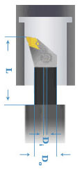
L = Unsupported length (overhang) of the boring bar [inch or mm]

E = Modulus of elasticity (in tension) for the boring bar material [psi or N/mm²]

Steel Modulus of elasticity = 30,000,000 psi

Steel Modulus of elasticity = 206,843 N/mm2

Heavy Metal (Tungsten alloy) modulus of elasticity = 48,000,000 psi

Heavy Metal (Tungsten alloy) modulus of elasticity = 330,948 N/mm2 

Carbide Modulus of elasticity = 80,000,000 psi

Carbide Modulus of elasticity = 551,581 N/mm2  

Note: The stated values are specific to Kennametal boring bars.

I = Moment of inertia for the boring bar cross-sectional area

Moment of Inertia for a solid cylindrical bar = π × DOD4 ÷ 64

Moment of Inertia for a hollow cylindrical bar = π × (DOD4 - DID4) ÷ 64

To use the boring bar deflection formula you must calculate the required cutting force (F), measure the boring bar’s overhang (L), select the correct modulus of elasticity for the boring bar (E), and calculate the moment of inertia for the boring bar’s cross-sectional area (I). Once those items are input into the formula the resulting outcome will be the amount of deflection (given as a distance). 

If the resulting deflection is unacceptable; recalculate using a boring bar with a greater modulus of elasticity or a boring bar with a larger moment of inertia. 

Deflection should be minimized but balanced against what is possible, based on the intended boring operation (depth and width). 

You are about to add to your My Solutions page. Do you want to proceed?
product-image
Please adjust the following properties from

ISO Catalog Number

ANSI Catalog Number

to find similar products.

The following files are available

Please select a file to download

Models

Product data

You should be logged to see your dashboard information
Session expired due to inactivity, please login again
The product/s () you were trying to add to the cart is/are not available, please contact customer service
item(s) successfully added to the cart
View Cart

. Please enter the desired qty for the material(s) you want to include in your promotion or Proceed Without Promotion and only your base materials will be added to the cart.

Minimum quantity should be

SAP Material NumberISO Catalog NumberGrade  

You are about to leave the Solution building process.

Are you sure you want to leave?