Produkt ähnlich wie:
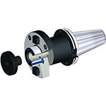
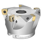
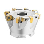
7792VXD12 Series • Shell Mill • Inch
High-Feed copy milling cutter for multiple materials.
Material Nummer5656919
ISO Katalog NummerC7792VXD12-A3.00Z8RANSI Katalog NummerC7792VXD12-A3.00Z8R
- P Stahl
- M Rostfreier Stahl
- K Gusseisen
- N NE-Metalle
- S Hochwarmfeste Legierungen
- H Gehärtete Werkstoffe
Spiral Circular
Slotting: Shoulder
Planfräsen
Spiralförmiges Interpolieren
Schräg-Eintauchfräsen Ins Volle
Auskammern
Senken
Tauchfräsen: Kugelkopf / Vollradius
Inclined Square End Mill
Sending to {{cadTool}} in progress...
Downloaded file will be available after import in the {{cadTool}} tool library.
- Überblick
- Anwendungsdaten
- Herunterladen
- Kompatible Teile Maschinenseite
- Kompatible Teile Werkstückseite
- Ersatzteile
- Bewertung
- F&A
| Material Nummer | 5656919 |
| ISO Katalog Nummer | C7792VXD12-A3.00Z8R |
| ANSI Katalog Nummer | C7792VXD12-A3.00Z8R |
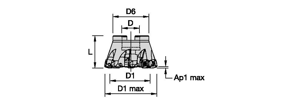
| [D1MAX] Schnittdurchmesser max. | 76.2 mm |
| [D1MAX] Schnittdurchmesser max. | 3 in |
| [D1] Effektiver Schneidendurchmesser | 57.81 mm |
| [D1] Effektiver Schneidendurchmesser | 2.276 in |
| [D] Adapter/Schaft/Bohrungsdurchmesser | 25.4 mm |
| [D] Adapter/Schaft/Bohrungsdurchmesser | 1 in |
| [D6] Nabendurchmesser | 50 mm |
| [D6] Nabendurchmesser | 1.969 in |
| [L] Gesamtlänge | 50 mm |
| [L] Gesamtlänge | 1.969 in |
| [AP1MAX] 1. maximale Schnitttiefe | 2.5 mm |
| [AP1MAX] 1. maximale Schnitttiefe | .098 in |
| [Z] Anzahl der Spannuten | 8 |
Werkstoffe
- Stahl
- Rostfreier Stahl
- Gusseisen
- NE-Metalle
- Hochwarmfeste Legierungen
- Gehärtete Werkstoffe
Uses and application
Spiral Circular
Slotting: Shoulder
Planfräsen
Spiralförmiges Interpolieren
Schräg-Eintauchfräsen Ins Volle
Auskammern
Senken
Tauchfräsen: Kugelkopf / Vollradius
Inclined Square End Mill
Features and benefits
- Internal coolant supply
- Positive design to support low cutting forces and applications with long overhang
Lösung erstellen, um Vorschübe und Geschwindigkeiten zu berechnen
Nachdem Sie eine Lösung erstellt haben, wählen Sie einfach das Symbol für Vorschübe und Geschwindigkeiten und unser System gibt Ihnen Empfehlungen. Sie können die Informationen anpassen, indem Sie Ihre Maschine und Spezifikationen hinzufügen oder Anpassungen mithilfe der Schieberegler vornehmen.
Insert Selection
Auswahlhilfe für Wendeschneidplatten • IC 12
| 7792 Series • IC12 • Insert Selection Guide | ||||||
| Werkstoffgruppe | Leichte Bearbeitung | Allgemeine Anwendung | Schruppbearbeitung | |||
| – | (Leicht schneidende Geometrie) | – | (Stabile Geometrie) | |||
| – | Verschleiß- festigkeit |  | Zähigkeit | |||
| – | Geometrie | Sorte | Geometrie | Sorte | Geometrie | Sorte |
| P1-P2 | ...M41 | KCPM40 | …M41 | KCPM40 | …GP | KCPM40 |
| P3-P4 | ...M41 | KCPM40 | …D411 | SP6519 | …D41 | KCPM40 |
| P5-P6 | ...M41 | KCPM40 | ...D41 | SP6519 | ...D41 | X500 |
| M1-M2 | ...M41 | KCSM40 | ...D411 | KCSM40 | ...D41 | KCSM40 |
| M3 | ...M41 | KCSM40 | ...D41 | KCSM40 | ...D41 | KCSM40 |
| K1-K2 | …M | KCK20B | …M | KCK20B | …D | KCPK30 |
| K3 | …M | KCK20B | …M | KCK20B | …D | KCPK30 |
| N1-N2 | – | – | – | – | – | – |
| N3 | – | – | – | – | – | – |
| S1-S2 | ...M41 | X500 | ...D411 | KCSM40 | ...D41 | KCSM40 |
| S3 | ...M41 | X500 | ...D411 | KCSM40 | ...D41 | KCSM40 |
| S4 | ...M41 | X500 | ...D411 | KCSM40 | ...D41 | KCSM40 |
| H1 | …M | KCKP10 | …M | KCKP10 | …D | KCPM40 |
Feeds
| 7792 Series • IC12 • Recommended Starting Feeds [IPT] | |||||||
| Schneidkörper- Geometrie | Empfohlener Start-Vorschub pro Zahn (fz) im Verhältnis zur radialen Schnitttiefe (ae) in % | ||||||
| DOC | 30% | 40–100% | |||||
| (Inch) | L | M | H | L | M | H | |
| .S..D | 0.1 | 0.009 | 0.024 | 0.036 | 0.009 | 0.022 | 0.032 |
| .S..D | 0.7 | 0.011 | 0.028 | 0.042 | 0.010 | 0.026 | 0.038 |
| .S..D | 0.55 | 0.013 | 0.031 | 0.047 | 0.012 | 0.029 | 0.043 |
| .E..D41 | 0.1 | 0.007 | 0.021 | 0.033 | 0.006 | 0.019 | 0.030 |
| .E..D41 | 0.7 | 0.008 | 0.025 | 0.039 | 0.007 | 0.023 | 0.036 |
| .E..D41 | 0.55 | 0.009 | 0.028 | 0.044 | 0.008 | 0.026 | 0.040 |
| .E..D411 | 0.1 | 0.007 | 0.021 | 0.033 | 0.006 | 0.019 | 0.030 |
| .E..D411 | 0.7 | 0.008 | 0.025 | 0.039 | 0.007 | 0.023 | 0.036 |
| .E..D411 | 0.55 | 0.009 | 0.028 | 0.044 | 0.008 | 0.026 | 0.040 |
| .S..GP | 0.1 | 0.009 | 0.024 | 0.035 | 0.009 | 0.022 | 0.032 |
| .S..GP | 0.7 | 0.011 | 0.028 | 0.042 | 0.010 | 0.026 | 0.038 |
| .S..GP | 0.55 | 0.013 | 0.031 | 0.047 | 0.012 | 0.029 | 0.043 |
| .S...M | 0.072 | 0.009 | 0.024 | 0.036 | 0.009 | 0.022 | 0.032 |
| .S...M | 0.55 | 0.013 | 0.031 | 0.047 | 0.012 | 0.029 | 0.043 |
| .E...M41 | 0.072 | 0.007 | 0.021 | 0.033 | 0.006 | 0.019 | 0.030 |
| .E..M41 | 0.55 | 0.009 | 0.028 | 0.044 | 0.008 | 0.026 | 0.040 |
| L = Light Machining; M = Medium Machining; H = Heavy Machining NOTE: Use Light Machining values as starting feed rate. | |||||||
| 7792 Series • IC12 • Recommended Starting Feeds for Plunging [IPT] | ||||
| Schneidkörper- Geometrie |  | Programmierter Vorschub pro Zahn (fz) | ||
| L | M | H | ||
| .S..D | 0.004 | 0.009 | 0.014 | |
| .E..D41 | 0.003 | 0.008 | 0.012 | |
| .E..D411 | 0.003 | 0.008 | 0.012 | |
| .S..GP | 0.004 | 0.009 | 0.014 | |
| .S..M | 0.004 | 0.009 | 0.014 | |
| .E..M41 | 0.003 | 0.008 | 0.012 | |
| L = Light Machining; M = Medium Machining; H = Heavy Machining NOTE: Use Light Machining values as starting feed rate. | ||||
| 7792 Series • IC12 • Recommended Starting Feeds [mm/th] | |||||||
| Schneidkörper- Geometrie | Empfohlener Start-Vorschub pro Zahn (fz) im Verhältnis zur radialen Schnitttiefe (ae) in % | ||||||
| DOC | 30% | 40–100% | |||||
| (mm) | L | M | H | L | M | H | |
| .S..D | 2,5 | 0,24 | 0,61 | 0,89 | 0,22 | 0,55 | 0,82 |
| .S..D | 1,7 | 0,29 | 0,73 | 1,08 | 0,27 | 0,67 | 0,98 |
| .S..D | 1,3 | 0,33 | 0,83 | 1,22 | 0,30 | 0,76 | 1,12 |
| .E..D41 | 2,5 | 0,17 | 0,54 | 0,83 | 0,15 | 0,49 | 0,76 |
| .E..D41 | 1,7 | 0,20 | 0,64 | 1,00 | 0,19 | 0,59 | 0,92 |
| .E..D41 | 1,3 | 0,23 | 0,73 | 1,14 | 0,21 | 0,67 | 1,04 |
| .E..D411 | 2,5 | 0,17 | 0,54 | 0,83 | 0,15 | 0,49 | 0,76 |
| .E..D411 | 1,7 | 0,20 | 0,64 | 1,00 | 0,19 | 0,59 | 0,92 |
| .E..D411 | 1,3 | 0,23 | 0,73 | 1,14 | 0,21 | 0,67 | 1,04 |
| .S..GP | 2,5 | 0,24 | 0,61 | 0,91 | 0,22 | 0,55 | 0,83 |
| .S..GP | 1,7 | 0,29 | 0,73 | 1,10 | 0,27 | 0,67 | 1,00 |
| .S..GP | 1,3 | 0,33 | 0,83 | 1,25 | 0,30 | 0,76 | 1,14 |
| .S...M | 1,84 | 0,24 | 0,61 | 0,89 | 0,22 | 0,55 | 0,82 |
| .S...M | 1,3 | 0,33 | 0,83 | 1,22 | 0,30 | 0,76 | 1,12 |
| .E..M41 | 1,84 | 0,17 | 0,54 | 0,83 | 0,15 | 0,49 | 0,76 |
| .E..M41 | 1,3 | 0,23 | 0,73 | 1,14 | 0,21 | 0,67 | 1,04 |
| L = Light Machining; M = Medium Machining; H = Heavy Machining NOTE: Use Light Machining values as starting feed rate. | |||||||
| 7792 Series • IC12 • Recommended Starting Feeds for Plunging [mm/th] | ||||
| Schneidkörper- Geometrie |  | Programmierter Vorschub pro Zahn (fz) | ||
| L | M | H | ||
| .S..D | 0,10 | 0,25 | 0,38 | |
| .E..D41 | 0,07 | 0,23 | 0,35 | |
| .E..D411 | 0,07 | 0,23 | 0,35 | |
| .S..GP | 0,10 | 0,25 | 0,38 | |
| .S..M | 0,10 | 0,25 | 0,38 | |
| .E..M41 | 0,07 | 0,23 | 0,35 | |
| L = Light Machining; M = Medium Machining; H = Heavy Machining NOTE: Use Light Machining values as starting feed rate. | ||||
Speeds
| 7792 Series IC12 • Recommended Starting Speed [SFM] | ||||||||||||||||||||||||||||||||||
| Schneidstoffsorte | KC522M | KC725M | KCK15 | KCPK30 | KCKP10 | KCK20B | KCPM40 | KCSM40 | SP6519 | X400 | X500 | |||||||||||||||||||||||
| Chip Thickness hex Inch | Min. | Max. | Min. | Max. | Min. | Max. | Min. | Max. | Min. | Max. | Min. | Max. | Min. | Max. | Min. | Max. | Min. | Max. | Min. | Max. | Min. | Max. | ||||||||||||
| Werkstoffgruppe | Max. | Startwert | Min. | Max. | Startwert | Min. | Max. | Startwert | Min. | Max. | Startwert | Min. | Max. | Startwert | Min. | Max. | Startwert | Min. | Max. | Startwert | Min. | Max. | Startwert | Min. | Max. | Startwert | Min. | Max. | Startwert | Min. | Max. | Startwert | Min. | |
| P | 1 | 1085 | 935 | 885 | 855 | 755 | 705 | – | – | – | 1495 | 1295 | 1215 | 985 | 970 | 855 | – | – | – | 970 | 855 | 805 | 1150 | 1050 | 985 | 970 | 705 | 425 | 855 | 625 | 395 | 885 | 655 | 425 |
| 2 | 900 | 785 | 655 | 720 | 625 | 525 | – | – | – | 920 | 835 | 755 | 1015 | 900 | 785 | – | – | – | 820 | 705 | 590 | 985 | 885 | 720 | 855 | 625 | 375 | 755 | 560 | 345 | 785 | 920 | 375 | |
| 3 | 835 | 705 | 575 | 655 | 560 | 460 | – | – | – | 835 | 755 | 675 | 900 | 785 | 675 | – | – | – | 755 | 640 | 525 | 920 | 785 | 640 | 755 | 540 | 330 | 655 | 490 | 310 | 690 | 510 | 330 | |
| 4 | 740 | 605 | 490 | 590 | 490 | 395 | – | – | – | 740 | 605 | 525 | 785 | 675 | 525 | – | – | – | 675 | 560 | 445 | 785 | 675 | 540 | 575 | 410 | 245 | 490 | 360 | 230 | 525 | 395 | 245 | |
| 5 | 605 | 560 | 490 | 490 | 445 | 395 | – | – | – | 625 | 560 | 490 | 675 | 525 | 410 | – | – | – | 560 | 510 | 445 | 655 | 590 | 525 | 460 | 345 | 230 | – | – | – | 425 | 330 | 230 | |
| 6 | 540 | 410 | 330 | 425 | 330 | 260 | – | – | – | 525 | 445 | 360 | 525 | 410 | 360 | – | – | – | 490 | 375 | 295 | 590 | 460 | 330 | 395 | 280 | 165 | – | – | – | 360 | 260 | 165 | |
| M | 1 | 675 | 590 | 540 | 560 | 490 | 445 | – | – | – | 675 | 605 | 510 | – | – | – | – | – | – | 640 | 560 | 510 | 855 | 690 | 605 | 885 | 640 | 375 | – | – | – | 820 | 605 | 375 |
| 2 | 605 | 525 | 425 | 510 | 425 | 360 | – | – | – | 605 | 525 | 460 | – | – | – | – | – | – | 575 | 490 | 410 | 770 | 590 | 475 | 770 | 560 | 345 | – | – | – | 720 | 525 | 330 | |
| 3 | 460 | 395 | 310 | 375 | 330 | 260 | – | – | – | 475 | 425 | 375 | – | – | – | – | – | – | 425 | 375 | 295 | 575 | 475 | 360 | 640 | 460 | 280 | – | – | – | 590 | 425 | 260 | |
| K | 1 | 755 | 675 | 605 | – | – | – | 1380 | 1265 | 1115 | 970 | 870 | 785 | 1345 | 1085 | 785 | 1180 | 950 | 805 | – | – | – | – | – | – | – | – | – | – | – | – | – | – | – |
| 2 | 590 | 525 | 490 | – | – | – | 1100 | 970 | 900 | 770 | 690 | 625 | 920 | 805 | 625 | 920 | 755 | 640 | – | – | – | – | – | – | – | – | – | – | – | – | – | – | – | |
| 3 | 490 | 445 | 395 | – | – | – | 920 | 820 | 755 | 640 | 575 | 525 | 785 | 640 | 525 | 690 | 575 | 460 | – | – | – | – | – | – | – | – | – | – | – | – | – | – | – | |
| N | 1 | – | – | – | – | – | – | – | – | – | – | – | – | – | – | – | – | – | – | – | – | – | – | – | – | – | – | – | – | – | – | – | – | – |
| 2 | – | – | – | – | – | – | – | – | – | – | – | – | – | – | – | – | – | – | – | – | – | – | – | – | – | – | – | – | – | – | – | – | – | |
| 3 | – | – | – | – | – | – | – | – | – | – | – | – | – | – | – | – | – | – | – | – | – | – | – | – | – | – | – | – | – | – | – | – | – | |
| S | 1 | 130 | 115 | 80 | 115 | 100 | 80 | – | – | – | – | – | – | – | – | – | – | – | – | 130 | 115 | 100 | 165 | 130 | 80 | 180 | 130 | 65 | – | – | – | 150 | 115 | 80 |
| 2 | 130 | 115 | 80 | 115 | 100 | 80 | – | – | – | – | – | – | – | – | – | – | – | – | 130 | 115 | 100 | 180 | 130 | 80 | 150 | 115 | 65 | – | – | – | 150 | 100 | 65 | |
| 3 | 165 | 130 | 80 | 150 | 115 | 80 | – | – | – | – | – | – | – | – | – | – | – | – | 165 | 130 | 100 | 215 | 150 | 100 | 180 | 130 | 80 | – | – | – | 165 | 130 | 80 | |
| 4 | 165 | 150 | 115 | 165 | 150 | 100 | – | – | – | 165 | 150 | 115 | – | – | – | – | – | – | 180 | 165 | 115 | 245 | 195 | 130 | 260 | 180 | 115 | – | – | – | 195 | 165 | 115 | |
| H | 1 | 395 | 295 | 230 | – | – | – | – | – | – | – | – | – | 460 | 360 | 295 | – | – | – | – | – | – | – | – | – | – | – | – | 310 | 230 | 150 | – | – | – |
| 2 | – | – | – | – | – | – | – | – | – | – | – | – | – | – | – | – | – | – | – | – | – | – | – | – | – | – | – | 260 | 195 | 115 | – | – | – | |
| Recommended Starting Speed are pointing to 90° Shoulder Milling . Starting Speed for Face and Copy Milling can be Increased by 20 %. As the average chip thickness increases, speed should be decreased. Material groups P, M, K and H show recommended starting speeds for dry machining. For wet machining, reduce speed by 20%. Material groups N and S show recommended starting speeds for wet machining. Not recommended for dry machining. | ||||||||||||||||||||||||||||||||||
Empfohlene Startwerte für Schnittgeschwindigkeiten [m/min]
| 7792 Series IC12 • Recommended Starting Speed [m/min] | ||||||||||||||||||||||||||||||||||
| Schneidstoffsorte | KC522M | KC725M | KCK15 | KCPK30 | KCKP10 | KCK20B | KCPM40 | KCSM40 | SP6519 | X400 | X500 | |||||||||||||||||||||||
| Spandicke hex mm | Min. | Max. | Min. | Max. | Min. | Max. | Min. | Max. | Min. | Max. | Min. | Max. | Min. | Max. | Min. | Max. | Min. | Max. | Min. | Max. | Min. | Max. | ||||||||||||
| Werkstoffgruppe | Max. | Startwert | Min. | Max. | Startwert | Min. | Max. | Startwert | Min. | Max. | Startwert | Min. | Max. | Startwert | Min. | Max. | Startwert | Min. | Max. | Startwert | Min. | Max. | Startwert | Min. | Max. | Startwert | Min. | Max. | Startwert | Min. | Max. | Startwert | Min. | |
| P | 1 | 330 | 285 | 270 | 260 | 230 | 215 | – | – | – | 455 | 395 | 370 | 300 | 295 | 260 | – | – | – | 295 | 260 | 245 | 350 | 320 | 300 | 295 | 215 | 130 | 260 | 190 | 120 | 270 | 200 | 130 |
| 2 | 275 | 240 | 200 | 220 | 190 | 160 | – | – | – | 280 | 255 | 230 | 310 | 275 | 240 | – | – | – | 250 | 215 | 180 | 300 | 270 | 220 | 260 | 190 | 115 | 230 | 170 | 105 | 240 | 280 | 115 | |
| 3 | 255 | 215 | 175 | 200 | 170 | 140 | – | – | – | 255 | 230 | 205 | 275 | 240 | 205 | – | – | – | 230 | 195 | 160 | 280 | 240 | 195 | 230 | 165 | 100 | 200 | 150 | 95 | 210 | 155 | 100 | |
| 4 | 225 | 185 | 150 | 180 | 150 | 120 | – | – | – | 225 | 185 | 160 | 240 | 205 | 160 | – | – | – | 205 | 170 | 135 | 240 | 205 | 165 | 175 | 125 | 75 | 150 | 110 | 70 | 160 | 120 | 75 | |
| 5 | 185 | 170 | 150 | 150 | 135 | 120 | – | – | – | 190 | 170 | 150 | 205 | 160 | 125 | – | – | – | 170 | 155 | 135 | 200 | 180 | 160 | 140 | 105 | 70 | – | – | – | 130 | 100 | 70 | |
| 6 | 165 | 125 | 100 | 130 | 100 | 80 | – | – | – | 160 | 135 | 110 | 160 | 125 | 110 | – | – | – | 150 | 115 | 90 | 180 | 140 | 100 | 120 | 85 | 50 | – | – | – | 110 | 80 | 50 | |
| M | 1 | 205 | 180 | 165 | 170 | 150 | 135 | – | – | – | 205 | 185 | 155 | – | – | – | – | – | – | 195 | 170 | 155 | 260 | 210 | 185 | 270 | 195 | 115 | – | – | – | 250 | 185 | 115 |
| 2 | 185 | 160 | 130 | 155 | 130 | 110 | – | – | – | 185 | 160 | 140 | – | – | – | – | – | – | 175 | 150 | 125 | 235 | 180 | 145 | 235 | 170 | 105 | – | – | – | 220 | 160 | 100 | |
| 3 | 140 | 120 | 95 | 115 | 100 | 80 | – | – | – | 145 | 130 | 115 | – | – | – | – | – | – | 130 | 115 | 90 | 175 | 145 | 110 | 195 | 140 | 85 | – | – | – | 180 | 130 | 80 | |
| K | 1 | 230 | 205 | 185 | – | – | – | 420 | 385 | 340 | 295 | 265 | 240 | 410 | 330 | 240 | 360 | 290 | 245 | – | – | – | – | – | – | – | – | – | – | – | – | – | – | – |
| 2 | 180 | 160 | 150 | – | – | – | 335 | 295 | 275 | 235 | 210 | 190 | 280 | 245 | 190 | 280 | 230 | 195 | – | – | – | – | – | – | – | – | – | – | – | – | – | – | – | |
| 3 | 150 | 135 | 120 | – | – | – | 280 | 250 | 230 | 195 | 175 | 160 | 240 | 195 | 160 | 210 | 175 | 140 | – | – | – | – | – | – | – | – | – | – | – | – | – | – | – | |
| N | 1 | – | – | – | – | – | – | – | – | – | – | – | – | – | – | – | – | – | – | – | – | – | – | – | – | – | – | – | – | – | – | – | – | – |
| 2 | – | – | – | – | – | – | – | – | – | – | – | – | – | – | – | – | – | – | – | – | – | – | – | – | – | – | – | – | – | – | – | – | – | |
| 3 | – | – | – | – | – | – | – | – | – | – | – | – | – | – | – | – | – | – | – | – | – | – | – | – | – | – | – | – | – | – | – | – | – | |
| S | 1 | 40 | 35 | 25 | 35 | 30 | 25 | – | – | – | – | – | – | – | – | – | – | – | – | 40 | 35 | 30 | 50 | 40 | 25 | 55 | 40 | 20 | – | – | – | 45 | 35 | 25 |
| 2 | 40 | 35 | 25 | 35 | 30 | 25 | – | – | – | – | – | – | – | – | – | – | – | – | 40 | 35 | 30 | 55 | 40 | 25 | 45 | 35 | 20 | – | – | – | 45 | 30 | 20 | |
| 3 | 50 | 40 | 25 | 45 | 35 | 25 | – | – | – | – | – | – | – | – | – | – | – | – | 50 | 40 | 30 | 65 | 45 | 30 | 55 | 40 | 25 | – | – | – | 50 | 40 | 25 | |
| 4 | 50 | 45 | 35 | 50 | 45 | 30 | – | – | – | 50 | 45 | 35 | – | – | – | – | – | – | 55 | 50 | 35 | 75 | 60 | 40 | 80 | 55 | 35 | – | – | – | 60 | 50 | 35 | |
| H | 1 | 120 | 90 | 70 | – | – | – | – | – | – | – | – | – | 140 | 110 | 90 | – | – | – | – | – | – | – | – | – | – | – | – | 95 | 70 | 45 | – | – | – |
| 2 | – | – | – | – | – | – | – | – | – | – | – | – | – | – | – | – | – | – | – | – | – | – | – | – | – | – | – | 80 | 60 | 35 | – | – | – | |
| Recommended Starting Speed are pointing to 90° Shoulder Milling . Starting Speed for Face and Copy Milling can be Increased by 20 %. As the average chip thickness increases, speed should be decreased. Material groups P, M, K and H show recommended starting speeds for dry machining. For wet machining, reduce speed by 20%. Material groups N and S show recommended starting speeds for wet machining. Not recommended for dry machining. | ||||||||||||||||||||||||||||||||||
Anwendungsdaten
| 7792 Series IC12 • Ramping Application Data • Curved Edges • Inch | |||||
| D1 max | Eintauch- winkel (°) | ae max | Anstei- | DH min [Inch] - (min hole diameter) | DH min (min Bohrungsdurchmesser) |
| 1.25 | 1.85° | 0.362 | 0.526 | 1.133 | 1.921 |
| 1.50 | 0.95° | 0.362 | 0.770 | 2.133 | 2.921 |
| 2.00 | 0.9° | 0.362 | 1.276 | 3.133 | 3.921 |
| 2.50 | 0.6° | 0.362 | 1.776 | 4.133 | 4.921 |
| 3.00 | 0.45° | 0.362 | 2.276 | 5.133 | 5.921 |
| 4.00 | 0.31° | 0.362 | 3.270 | 7.133 | 7.921 |
| 5.00 | 0.24° | 0.362 | 4.270 | 9.133 | 9.921 |
| 6.00 | 0.19° | 0.362 | 5.270 | 11.133 | 11.921 |
| NOTE: Maximum ramp angle decreases as nose radius increases. | |||||
| 7792 Series IC12 • Ramping Application Data • Straight-Edged Inserts • Inch | |||||
| D1 max | Eintauch- winkel (°) | ae max | Anstei- | DH min [Inch] - (min hole diameter) | DH min (min Bohrungsdurchmesser) |
| 1.25 | 3.56° | 0.362 | 0.604 | 1.133 | 1.921 |
| 1.50 | 2.22° | 0.362 | 0.854 | 2.133 | 2.921 |
| 2.00 | 1.25° | 0.362 | 1.354 | 3.133 | 3.921 |
| 2.50 | 0.86° | 0.362 | 1.854 | 4.133 | 4.921 |
| 3.00 | 0.66° | 0.362 | 2.354 | 5.133 | 5.921 |
| 4.00 | 0.45° | 0.362 | 3.354 | 7.133 | 7.921 |
| 5.00 | 0.34° | 0.362 | 4.354 | 9.133 | 9.921 |
| 6.00 | 0.275° | 0.362 | 5.354 | 11.133 | 11.921 |
| NOTE: Maximum ramp angle decreases as nose radius increases. | |||||
| 7792 Series IC12 • Programing Data • Curved Edges • Inch [inch] | |||
| IC | Eckenradius | R | L |
| 06 | 0.031 | 0.057 | 0.016 |
| 09 | 0.031 | 0.079 | 0.028 |
| 0.047 | 0.089 | 0.026 | |
| 12 | 0.031 | 0.098 | 0.040 |
| 0.047 | 0.107 | 0.038 | |
| 16 | 0.047 | 0.164 | 0.057 |
| 7792 Series IC12 • Programing Data • Straight-Edged Inserts • Inch [inch] | |||
| IC | Eckenradius | R | L |
| 06 | 0.031 | 0.057 | 0.021 |
| 09 | 0.031 | 0.084 | 0.040 |
| 0.047 | 0.088 | 0.037 | |
| 12 | 0.031 | 0.097 | 0.052 |
| 0.047 | 0.109 | 0.050 | |
| 0.079 | 0.134 | 0.044 | |
| 16 | 0.047 | 0.140 | 0.072 |
| CNC Program • Corner Radius Definition The use of common CAD/CAM systems requires a round insert dimension to be known for cavity machining. For finish pass applications: Wiper facet for finishing use max. feed 0.031". | |||
| 7792 Series IC12 • Ramping Application Data • Curved Edges • Metric | |||||
| D1 max | Eintauch- winkel (°) | ae max | Anstei- | DH min [mm] - (min hole diameter) | DH min (min Bohrungsdurchmesser) |
| 32 | 1.8° | 9,2 | 10,6 | 42 | 62 |
| 35 | 1.8° | 9,2 | 16,6 | 48 | 68 |
| 40 | 1.4° | 9,2 | 21,6 | 58 | 78 |
| 42 | 1.3° | 9,2 | 23,6 | 62 | 82 |
| 50 | 0.9° | 9,2 | 31,6 | 78 | 98 |
| 52 | 0.8° | 9,2 | 33,6 | 82 | 102 |
| 63 | 0.6° | 9,2 | 44,6 | 104 | 124 |
| 66 | 0.5° | 9,2 | 47,6 | 110 | 130 |
| 80 | 0.5° | 9,2 | 61,6 | 138 | 158 |
| 100 | 0.3° | 9,2 | 81,6 | 178 | 198 |
| 125 | 0.2° | 9,2 | 106,6 | 228 | 248 |
| 160 | 0.2° | 9,2 | 141,6 | 298 | 318 |
| NOTE: Maximum ramp angle decreases as nose radius increases. | |||||
| 7792 Series IC12 • Ramping Application Data • Straight-Edged Inserts • Metric | |||||
| D1 max | Eintauch- winkel (°) | ae max | Anstei- | DH min [mm] - (min hole diameter) | DH min (min Bohrungsdurchmesser) |
| 32 | 3.1° | 9,2 | 15,6 | 42 | 62 |
| 35 | 2.45° | 9,2 | 18,6 | 48 | 68 |
| 40 | 1.8° | 9,2 | 23,6 | 58 | 78 |
| 42 | 1.6° | 9,2 | 25,6 | 62 | 82 |
| 50 | 1.1° | 9,2 | 33,6 | 78 | 98 |
| 52 | 1.1° | 9,2 | 35,6 | 82 | 102 |
| 63 | 0.8° | 9,2 | 46,6 | 104 | 124 |
| 66 | 0.75° | 9,2 | 49,6 | 110 | 130 |
| 80 | 0.55° | 9,2 | 63,6 | 138 | 158 |
| 100 | 0.4° | 9,2 | 83,6 | 178 | 198 |
| 125 | 0.3° | 9,2 | 108,6 | 228 | 248 |
| 160 | 0.25° | 9,2 | 143,6 | 298 | 318 |
| NOTE: Maximum ramp angle decreases as nose radius increases. | |||||
| 7792 Series IC12 • Programing Data • Curved Edges • Metric [mm] | |||
| IC | Eckenradius | R | L |
| 06 | 0,8 | 1,37 | 0,4 |
| 09 | 0,8 | 2,01 | 0,73 |
| 1,2 | 2,27 | 0,67 | |
| 12 | 0,8 | 2,5 | 1,02 |
| 1,2 | 2,73 | 0,97 | |
| 16 | 1,2 | 4,18 | 1,46 |
| 7792 Series IC12 • Programing Data • Straight-Edged Inserts • Metric [mm] | |||
| IC | Eckenradius | R | L |
| 06 | 0,8 | 1,46 | 0,529 |
| 09 | 0,8 | 2,13 | 1,025 |
| 1,2 | 2,25 | 0,95 | |
| 12 | 0,8 | 2,46 | 1,33 |
| 1,2 | 2,79 | 1,27 | |
| 2 | 3,42 | 1,13 | |
| 16 | 1,2 | 3,56 | 1,82 |
| CNC Program • Corner Radius Definition The use of common CAD/CAM systems requires a round insert dimension to be known for cavity machining. For finish pass applications: Wiper facet for finishing use max. feed 0,8mm. | |||
CAD Drawings Models
Can’t find the file type you’re looking for?
Product data
I have read and accepted the Terms & Conditions of use
