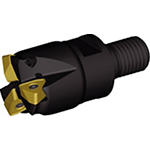
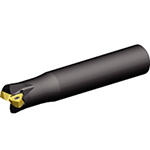
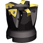
Produkt ähnlich wie:
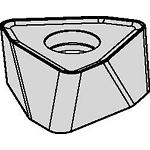
Wendeschneidplatten für KenFeed™ 2X • WOEJ09....GD
Wendeschneidplatten • WOEJ09...
Material Nummer5517767
ISO Katalog NummerWOEJ090512SRGDANSI Katalog NummerWOEJ090512SRGD
- P Stahl
- M Rostfreier Stahl
- S Hochwarmfeste Legierungen
- H Gehärtete Werkstoffe
Sending to {{cadTool}} in progress...
Downloaded file will be available after import in the {{cadTool}} tool library.
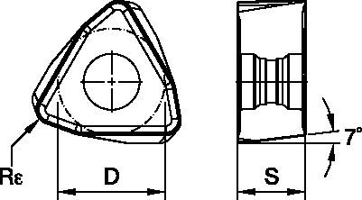
| Material Nummer | 5517767 |
| ISO Katalog Nummer | WOEJ090512SRGD |
| ANSI Katalog Nummer | WOEJ090512SRGD |
| Sorte | KCSM30 |
| [D] Wendeschneidplatten-Größe (Inkreis) | 8.9 mm |
| [D] Wendeschneidplatten-Größe (Inkreis) | 0.35 in |
| [S] Dicke der Wendeschneidplatte | 5.4 mm |
| [S] Dicke der Wendeschneidplatte | 0.213 in |
| [Rε] Eckenradius | 1.2 mm |
| [Rε] Eckenradius | 0.047 in |
| Schneidkanten pro Wendeschneidplatte | 6 |
Werkstoffe
- Stahl
- Rostfreier Stahl
- Hochwarmfeste Legierungen
- Gehärtete Werkstoffe
Grades

KCSM30
Das ultrafeine Substrat mit leistungsstarker TiAlN-PVD-Beschichtung ist eine ausgezeichnete Wahl für Titan, ist jedoch auch für hochtemperaturbeständige Legierungen und nicht rostende Stähle mit höheren Schnittgeschwindigkeiten für die leichte bis mittlere Bearbeitung geeignet. Erste Wahl für die Anwendung mit dünnen bis mittleren Spandicken, für die Trocken- und Nassbearbeitung.
Features and benefits
- Doppelseitige Wendeschneidplatte mit sechs Schneidkanten.
- Einzigartiges und stabiles Wendeschneidplattendesign für hohe Vorschübe (bis zu 2,5 mm pro Zahn).
- Die -HD-Geometrie ist die erste Wahl für Stähle, hochfeste Stähle und Gusseisen.
- Die -GD-Geometrie ermöglicht niedrigere Schnittkräfte und ist die erste Wahl für weiche Werkstoffe.
Lösung erstellen, um Vorschübe und Geschwindigkeiten zu berechnen
Nachdem Sie eine Lösung erstellt haben, wählen Sie einfach das Symbol für Vorschübe und Geschwindigkeiten und unser System gibt Ihnen Empfehlungen. Sie können die Informationen anpassen, indem Sie Ihre Maschine und Spezifikationen hinzufügen oder Anpassungen mithilfe der Schieberegler vornehmen.
Feeds
Empfohlene Startwerte für Vorschübe [mm]
| Schneidkörper- Geometrie | Empfohlener Start-Vorschub pro Zahn (fz) im Verhältnis zur radialen Schnitttiefe (ae) in % | Schneidkörper- Geometrie | ||||||||||||||
| 5% | 10% | 20% | 30% | 40–100% | ||||||||||||
| .S..GD | 1,15 | 2,42 | 3,84 | 0,82 | 1,71 | 2,67 | 0,61 | 1,26 | 1,96 | 0,53 | 1,10 | 1,70 | 0,49 | 1,01 | 1,55 | .S..GD |
| .S..HD | 1,15 | 2,78 | 4,27 | 0,82 | 1,96 | 2,94 | 0,61 | 1,44 | 2,16 | 0,53 | 1,26 | 1,87 | 0,49 | 1,15 | 1,71 | .S..HD |
| Leichte Bearbeitung | Allgemeine Anwendung | Schruppbearbeitung |
Recommended Starting Feeds [IPT]
| Leichte Bearbeitung | Allgemeine Anwendung | Schruppbearbeitung |
| Schneidkörper- Geometrie | Empfohlener Start-Vorschub pro Zahn (fz) im Verhältnis zur radialen Schnitttiefe (ae) in % | Schneidkörper- Geometrie | ||||||||||||||
| 5% | 10% | 20% | 30% | 40–100% | ||||||||||||
| .S..GD | .045 | .089 | .141 | .032 | .063 | .098 | .024 | .047 | .072 | .021 | .040 | .063 | .019 | .037 | .057 | .S..GD |
| .S..HD | .045 | .109 | .168 | .032 | .077 | .116 | .024 | .057 | .085 | .021 | .049 | .074 | .019 | .045 | .067 | .S..HD |
Speeds
Empfohlene Startwerte für Schnittgeschwindigkeiten [m/min]
| Werkstoffgruppe | KC522M | KC725M | KCK15 | KCPK30 | |||||||||
| P | 1 | 395 | 345 | 325 | 315 | 275 | 255 | – | – | – | 545 | 475 | 440 |
| 2 | 330 | 290 | 240 | 260 | 230 | 195 | – | – | – | 335 | 305 | 275 | |
| 3 | 305 | 255 | 215 | 240 | 205 | 170 | – | – | – | 305 | 275 | 250 | |
| 4 | 270 | 225 | 180 | 215 | 180 | 145 | – | – | – | 225 | 210 | 190 | |
| 5 | 225 | 200 | 180 | 180 | 160 | 145 | – | – | – | 310 | 275 | 255 | |
| 6 | 200 | 150 | 120 | 160 | 120 | 95 | – | – | – | 190 | 165 | – | |
| M | 1 | 245 | 215 | 200 | 205 | 180 | 165 | – | – | – | 250 | 220 | 190 |
| 2 | 225 | 190 | 160 | 185 | 160 | 130 | – | – | – | 225 | 195 | 170 | |
| 3 | 170 | 145 | 115 | 140 | 120 | 95 | – | – | – | 175 | 160 | 140 | |
| K | 1 | 275 | 250 | 220 | – | – | – | 505 | 460 | 410 | 355 | 320 | 285 |
| 2 | 215 | 195 | 180 | – | – | – | 400 | 355 | 330 | 280 | 255 | 230 | |
| 3 | 180 | 160 | 145 | – | – | – | 335 | 300 | 275 | 235 | 210 | 195 | |
| N | 1 | – | – | – | – | – | – | – | – | – | – | – | – |
| 2 | – | – | – | – | – | – | – | – | – | – | – | – | |
| S | 1 | 50 | 45 | 35 | 45 | 35 | 30 | – | – | – | – | – | – |
| 2 | 50 | 45 | 35 | 45 | 35 | 30 | – | – | – | – | – | – | |
| 3 | 60 | 50 | 35 | 55 | 45 | 30 | – | – | – | – | – | – | |
| 4 | 85 | 60 | 45 | 75 | 55 | 35 | – | – | – | – | – | – | |
| H | 1 | 145 | 110 | 85 | – | – | – | – | – | – | – | – | – |
| 2 | – | – | – | – | – | – | – | – | – | – | – | – | |
| 3 | – | – | – | – | – | – | – | – | – | – | – | – | |
Anwendungsdaten
Maximalwerte für lineares und spiralförmige Interpolation in das volle Material • Zoll
| Fräser-Typ | Katalognummer | Empfohlener linearer Schräg-Ein- tauchwinkel | Maximaler Schräg-Ein- tauchwinkel (nicht linear) | Maximaler Eintauchwinkel bei spiralförmiger Interpolation | min. Bohrungs- durchmesser (DH min) | max. Flachbohrungs- durchmesser (DH1 max) | max. Bohrungsdurchmesser (keine Flachbohrung) |
| Screw-On | KF2X100W0902M12L138 | 3.5° | 5.2° | 3.1° | 1.291 | 1.35 | 2.0 |
| KF2X125W0902M16L169 | 1.9° | 2.8° | 1.7° | 1.813 | 1.87 | 2.5 | |
| KF2X125W0903M16L169 | 1.9° | 2.8° | 1.7° | 1.813 | 1.87 | 2.5 | |
| KF2X150W0903M16L169 | 1.4° | 2.1° | 1.2° | 2.310 | 2.37 | 3.0 | |
| KF2X150W0904M16L169 | 1.4° | 2.1° | 1.2° | 2.310 | 2.37 | 3.0 | |
| End Mills | KF2X100W0902C100L600 | 3.5° | 5.2° | 3.1° | 1.291 | 1.35 | 2.0 |
| KF2X100W0902C100L800 | 3.5° | 5.2° | 3.1° | 1.291 | 1.35 | 2.0 | |
| KF2X125W0903C125L600 | 1.9° | 2.8° | 1.7° | 1.813 | 1.87 | 2.5 | |
| KF2X125W0903C125L800 | 1.9° | 2.8° | 1.7° | 1.813 | 1.87 | 2.5 | |
| KF2X150W0903C125L600 | 1.4° | 2.1° | 1.2° | 2.310 | 2.37 | 3.0 | |
| KF2X150W0903C125L800 | 1.4° | 2.1° | 1.2° | 2.310 | 2.37 | 3.0 | |
| Face Mills | KF2X150W0904S050L157 | 1.4° | 2.1° | 1.2° | 2.310 | 2.37 | 3.0 |
| KF2X200W0905S075L157 | 1.0° | 1.4° | 0.8° | 3.307 | 3.37 | 4.0 | |
| KF2X200W0906S075L157 | 1.0° | 1.4° | 0.8° | 3.307 | 3.37 | 4.0 | |
| KF2X250W0906S075L175 | 0.7° | 1.1° | 0.6° | 4.305 | 4.36 | 5.0 | |
| KF2X300W0907S100L175 | 0.6° | 1.0° | 0.5° | 5.303 | 5.36 | 6.0 | |
| KF2X300W0907S125L200 | 0.6° | 1.0° | 0.5° | 5.303 | 5.36 | 6.0 |
General Programming Information for Applying KenFeed 2X • IC 09
| Rt | Wt | t |
| .110 | .312 | .045 |
Maximalwerte für lineares und spiralförmige Interpolation in das volle Material • Zoll
| Fräser-Typ | Katalognummer | Empfohlener linearer Schräg-Ein- tauchwinkel | Maximaler Schräg-Ein- tauchwinkel (nicht linear) | Maximaler Eintauchwinkel bei spiralförmiger Interpolation | min. Bohrungs- durchmesser (DH min) | max. Flachbohrungs- durchmesser (DH1 max) | max. Bohrungsdurchmesser (keine Flachbohrung) |
| Screw-On | KF2X2X25Z02M12WO09 | 3.6° | 5.4° | 3.1° | 26,5 | 33,7 | 50 |
| KF2X32Z03M16WO09 | 1.8° | 2.7° | 1.7° | 41,2 | 48,4 | 64 | |
| KF2X35Z03M16WO09 | 1.6° | 2.4° | 1.4° | 46,8 | 54,0 | 70 | |
| KF2X42Z04M16WO09 | 1.2° | 1.9° | 0.8° | 68,7 | 75,9 | 84 | |
| End Mills | KF2X25Z02A25WO09L140 | 3.6° | 5.4° | 3.1° | 26,5 | 33,7 | 50 |
| KF2X25Z02A25WO09L200 | 3.6° | 5.4° | 3.1° | 26,5 | 33,7 | 50 | |
| KF2X25Z02A25WO09L300 | 3.6° | 5.4° | 3.1° | 26,5 | 33,7 | 50 | |
| KF2X28Z02A25WO09L200 | 3.1° | 4.6° | 2.5° | 31,6 | 38,8 | 56 | |
| KF2X32Z03A32WO09L150 | 1.8° | 2.7° | 1.7° | 41,2 | 48,4 | 64 | |
| KF2X32Z03A32WO09L200 | 1.8° | 2.7° | 1.7° | 41,2 | 48,4 | 64 | |
| KF2X32Z03A32WO09L300 | 1.8° | 2.7° | 1.7° | 41,2 | 48,4 | 64 | |
| KF2X35Z03A32WO09L200 | 1.6° | 2.4° | 1.4° | 46,8 | 54,0 | 70 | |
| Face Mills | KF2X40Z04WO09 | 1.3° | 2.0° | 1.2° | 56,4 | 63,6 | 80 |
| KF2X50Z05WO09 | 1.0° | 1.5° | 0.8° | 76,7 | 83,9 | 100 | |
| KF2X52Z05WO09 | 1.0° | 1.4° | 0.8° | 80,7 | 87,9 | 104 | |
| KF2X63Z05S22WO09 | 0.8° | 1.2° | 0.6° | 102,7 | 109,9 | 126 | |
| KF2X63Z05WO09 | 0.8° | 1.2° | 0.6° | 102,7 | 109,9 | 126 | |
| KF2X66Z06S22WO09 | 0.7° | 1.1° | 0.5° | 108,7 | 115,9 | 132 | |
| KF2X66Z06WO09 | 0.7° | 1.1° | 0.5° | 108,7 | 115,9 | 132 | |
| KF2X80Z07WO09 | 0.6° | 0.9° | 0.4° | 136,6 | 143,8 | 160 |
Maximalwerte für lineares und spiralförmige Interpolation in das volle Material • Zoll
| Durchmesser | Max. Tauchwinkel | Maximaler Eintauchwinkel bei spiralförmiger Interpolation | Max. Eintauchtiefe | min. Bohrungs- durchmesser (DH min) | max. Flachbohrungs- durchmesser (DH1 max) | max. Bohrungsdurchmesser (keine Flachbohrung) |
| 1.50 | 5.5° | 1.93° | 0.076 | 1.90 | 2.22 | 3.00 |
| 2.00 | 4.4° | 1.18° | 0.076 | 2.86 | 3.22 | 4.00 |
| 2.50 | 3.0° | 0.85° | 0.076 | 3.85 | 4.22 | 5.00 |
| 3.00 | 2.3° | 0.67° | 0.076 | 4.84 | 5.21 | 6.00 |
| 4.00 | 1.6° | 0.47° | 0.076 | 6.84 | 7.21 | 8.00 |
| 5.00 | 1.2° | 0.36° | 0.076 | 8.84 | 9.21 | 10.00 |
Insert Selection
| Werkstoffgruppe | Leichte Bearbeitung | Allgemeine Anwendung | Schruppbearbeitung | |||
| – | (Leicht schneidende Geometrie) | – | (Stabile Geometrie) | |||
| – | Verschleiß- festigkeit |  | Zähigkeit | |||
| – | Geometrie | Sorte | Geometrie | Sorte | Geometrie | Sorte |
| P1–P2 | .S..GD | KCPK30 | .S..GD | KCPM40 | .S..HD | KCPM40 |
| P3–P4 | .S..GD | KCPK30 | .S..GD | KCPM40 | .S..HD | KCPM40 |
| P5–P6 | .S..GD | KCPK30 | .S..GD | KC725M | .S..HD | KC725M |
| M1–M2 | .S..GD | KC522M | .S..GD | KC725M | .S..HD | KC725M |
| M3 | .S..GD | KCPK30 | .S..GD | KCPM40 | .S..HD | KCPM40 |
| K1–K2 | .S..HD | KCK15 | .S..HD | KCK15 | .S..HD | KCK15 |
| K3 | .S..GD | KCPK30 | .S..HD | KCK15 | .S..HD | KCPK30 |
| N1–N2 | – | – | – | – | – | – |
| N3 | – | – | – | – | – | – |
| S1–S2 | .S..GD | KC522M | .S..GD | KC725M | .S..HD | KC725M |
| S3 | .S..GD | KC725M | .S..GD | KCPM40 | .S..HD | KCPM40 |
| S4 | .S..GD | KC522M | .S..HD | KC522M | .S..HD | KC725M |
| H1 | – | – | – | – | – | – |
Insert Selection Guide
| Werkstoffgruppe | Leichte Bearbeitung | Allgemeine Anwendung | Schruppbearbeitung | |||
| (Leicht schneidende Geometrie) | (Stabile Geometrie) | |||||
| Verschleiß- festigkeit |  | Zähigkeit | ||||
| Geometrie | Sorte | Geometrie | Sorte | Geometrie | Sorte | |
| P1–P2 | .S..GD | KCPK30 | .S..GD | KCPM40 | .S..HD | KCPM40 |
| P3–P4 | .S..GD | KCPK30 | .S..GD | KCPM40 | .S..HD | KCPM40 |
| P5–P6 | .S..GD | KCPK30 | .S..GD | KC725M | .S..HD | KC725M |
| M1–M2 | .S..GD | KC522M | .S..GD | KC725M | .S..HD | KC725M |
| M3 | .S..GD | KCPK30 | .S..GD | KCPM40 | .S..HD | KCPM40 |
| K1–K2 | .S..HD | KCK15 | .S..HD | KCK15 | .S..HD | KCK15 |
| K3 | .S..GD | KCPK30 | .S..HD | KCK15 | .S..HD | KCPK30 |
| N1–N2 | – | – | – | – | – | – |
| N3 | – | – | – | – | – | – |
| S1–S2 | .S..GD | KC522M | .S..GD | KC725M | .S..HD | KC725M |
| S3 | .S..GD | KC725M | .S..GD | KCPM40 | .S..HD | KCPM40 |
| S4 | .S..GD | KC522M | .S..HD | KC522M | .S..HD | KC725M |
| H1 | – | – | – | – | – | – |
I have read and accepted the Terms & Conditions of use
CAD Drawings Models
Can’t find the file type you’re looking for?
Product data
