Produkt ähnlich wie:
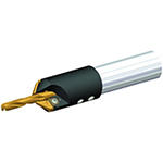
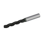
K105 (~5 x D) • K10 • A-Schaft • Bohrer Typ TF
Bohrer Typ TF • Hohe Zerspanungsvolumen • Keine innere Kühlmittelzuführung
Material Nummer1773989
ISO Katalog NummerK105A05156ANSI Katalog NummerDWG 1682386
Bohren
Bohren: Schräge Austrittsfläche
Außenkühlung: Bohren
Zylinderschaft – ohne Spannfläche ≤h6
Spiralwinkel: 30°
Bohrtiefe: 5x
Drilling: Cross-Hole Drilling
Sending to {{cadTool}} in progress...
Downloaded file will be available after import in the {{cadTool}} tool library.

| Material Nummer | 1773989 |
| ISO Katalog Nummer | K105A05156 |
| ANSI Katalog Nummer | DWG 1682386 |
| Sorte | KC7210 |
| [D1] Bohrerdurchmesser M | 13.0962 mm |
| [D1] Bohrerdurchmesser M | .5156 in |
| [L] Gesamtlänge | 124 mm |
| [L] Gesamtlänge | 4.881 in |
| [L3] Spannuten-Länge | 77 mm |
| [L3] Spannuten-Länge | 3.031 in |
| [L4] Maximale Bohrtiefe | 60 mm |
| [L4] Maximale Bohrtiefe | 2.362 in |
| [L5] Bohrerspitzenlänge | 3.27 mm |
| [L5] Bohrerspitzenlänge | .1287 in |
| [LS] Schaftlänge | 45.5 mm |
| [LS] Schaftlänge | 1.791 in |
| [D] Adapter/Schaft/Bohrungsdurchmesser | 14.2875 mm |
| [D] Adapter/Schaft/Bohrungsdurchmesser | .5625 in |
Uses and application
Bohren
Bohren: Schräge Austrittsfläche
Außenkühlung: Bohren
Zylinderschaft – ohne Spannfläche ≤h6
Spiralwinkel: 30°
Bohrtiefe: 5x
Drilling: Cross-Hole Drilling
Grades

KC7210
Zusammensetzung: Feinkörniges Hartmetallsubstrat mit PVD-TiAlN-Beschichtung mit verbesserter Warmfestigkeit.
Anwendung: Für die Trockenbearbeitung von Gusseisen bestens geeignet. Die verbesserte Warmfestigkeit des Substrats und die verschleißfeste TiAlN-Beschichtung bieten zusammen mit dem Bohrerdesign mit drei Spannuten höchstes Zerspanungsvolumen.
Features and benefits
- TF drills without through coolant for high metal removal rates and excellent hole quality in short chipping materials such as gray cast iron, ductile iron, and aluminum, as well as in short-hole titanium applications.
- Material-specific SC drill with three cutting edges for higher feed rates than with two-edged drills.
- Three spacious flutes for rapid chip evacuation.
- Three-margin lands deliver better hole quality and straightness than two-flute drills.
- TiAlN-coated KC7210™ grade for higher wear resistance at elevated speeds.
- Uncoated K10™ grade helps to prevent built-up edge in drilling aluminum and high-temp alloys.
Lösung erstellen, um Vorschübe und Geschwindigkeiten zu berechnen
Nachdem Sie eine Lösung erstellt haben, wählen Sie einfach das Symbol für Vorschübe und Geschwindigkeiten und unser System gibt Ihnen Empfehlungen. Sie können die Informationen anpassen, indem Sie Ihre Maschine und Spezifikationen hinzufügen oder Anpassungen mithilfe der Schieberegler vornehmen.
Toleranz
| Toleranz • Zoll | ||
| Nenndurchmesserbereich | D1 Toleranz m7 | D Toleranz h6 |
| .0002/.0006 | .0000/-.0003 | |
| .0002/.0008 | .0000/-.0004 | |
| .0003/.0010 | .0000/-.0004 | |
| .0003/.0011 | .0000/-.0005 | |
| Toleranz • Metrisch | ||
| Nenndurchmesserbereich | D1 Toleranz m7 | D Toleranz h6 |
| 0,004/0,016 | 0,000/-0,008 | |
| 0,006/0,021 | 0,000/-0,009 | |
| 0,007/0,025 | 0,000/-0,011 | |
| 0,008/0,029 | 0,000/-0,013 | |
Anwendungsdaten
Bohrer Typ TF • B105 • Sorte K10™ • Außenkühlung • Bohrerdurchmesser 0,1181-0,7874″ • Zoll
| Werkstoffgruppe |  |  | |||||||||||
| Schnittgeschwindigkeit | Metrisch | ||||||||||||
| Bereich | Empfohlene Vorschubrate (f) pro Umdrehung | ||||||||||||
| Min. | Startwert | Max. | 3,0 | 4,0 | 6,0 | 8,0 | 10,0 | 12,0 | 16,0 | 20,0 | |||
| K | 1 | 60 | 85 | 110 | mm/U | 0,11–0,20 | 0,12–0,20 | 0,16–0,28 | 0,20–0,35 | 0,22–0,42 | 0,24–0,50 | 0,28–0,61 | 0,30–0,68 |
| 2 | 70 | 70 | 90 | mm/U | 0,11–0,20 | 0,12–0,20 | 0,16–0,28 | 0,20–0,35 | 0,22–0,42 | 0,24–0,50 | 0,28–0,61 | 0,30–0,68 | |
| 3 | 50 | 50 | 70 | mm/U | 0,09–0,18 | 0,10–0,18 | 0,14–0,26 | 0,18–0,33 | 0,02–0,40 | 0,22–0,48 | 0,26–0,59 | 0,28–0,66 | |
| N | 1 | 100 | 210 | 410 | mm/U | 0,09–0,15 | 0,10–0,20 | 0,18–0,33 | 0,20–0,38 | 0,25–0,43 | 0,03–0,51 | 0,43–0,58 | 0,64–0,79 |
| 2 | 100 | 250 | 250 | mm/U | 0,10–0,19 | 0,12–0,21 | 0,18–0,33 | 0,25–0,42 | 0,30–0,50 | 0,35–0,58 | 0,44–0,74 | 0,52–0,88 | |
| 3 | 100 | 180 | 400 | mm/U | 0,09–0,16 | 0,10–0,20 | 0,12–0,26 | 0,16–0,36 | 0,20–0,40 | 0,24–0,45 | 0,30–0,50 | 0,34–0,60 | |
| 4 | 60 | 170 | 250 | mm/U | 0,08–0,15 | 0,13–0,18 | 0,18–0,33 | 0,20–0,36 | 0,23–0,38 | 0,33–0,46 | 0,38–0,48 | 0,58–0,76 | |
| S | 4 | 20 | 20 | 50 | mm/U | 0,03–0,05 | 0,04–0,07 | 0,07–0,09 | 0,09–0,12 | 0,11–0,15 | 0,13–0,18 | 0,17–0,24 | 0,22–0,30 |
| Werkstoffgruppe |  |  | |||||||||||
| Werkstoffgruppe | Schnittgeschwindigkeit | Zoll | |||||||||||
| Bereich | Empfohlene Vorschubrate (f) pro Umdrehung | ||||||||||||
| Min. | Startwert | Max. | 1/8 .125 | 3/16 .188 | 1/4 .250 | 5/16 .313 | 3/8 .375 | 1/2 .500 | 5/8 .625 | 3/4 .750 | |||
| K | 1 | 200 | 280 | 360 | IPR | .004–.008 | .005–.008 | .006–.011 | .008–.014 | .009–.017 | .009–.020 | .011–.024 | .012–.027 |
| 2 | 230 | 230 | 300 | IPR | .004–.008 | .005–.008 | .006–.011 | .008–.014 | .009–.017 | .009–.020 | .011–.024 | .012–.027 | |
| 3 | 160 | 160 | 230 | IPR | .004–.007 | .004–.007 | .006–.010 | .007–.013 | .001–.016 | .009–.019 | .010–.023 | .011–.026 | |
| N | 1 | 330 | 690 | 1340 | IPR | .004–.006 | .004–.008 | .007–.013 | .008–.015 | .010–.017 | .001–.020 | .017–.023 | .025–.031 |
| 2 | 330 | 820 | 820 | IPR | .004–.008 | .005–.008 | .007–.013 | .010–.017 | .012–.020 | .014–.023 | .017–.029 | .021–.035 | |
| 3 | 330 | 590 | 1310 | IPR | .004–.006 | .004–.008 | .005–.010 | .006–.014 | .008–.016 | .009–.018 | .012–.020 | .013–.024 | |
| 4 | 200 | 560 | 820 | IPR | .003–.006 | .005–.007 | .007–.013 | .008–.014 | .009–.015 | .013–.018 | .015–.019 | .023–.030 | |
| S | 4 | 70 | 70 | 160 | IPR | .001–.002 | .002–.003 | .003–.004 | .004–.005 | .004–.006 | .005–.007 | .007–.009 | .009–.012 |
 |  | ||||||||||||
| Schnittgeschwindigkeit | Metrisch | ||||||||||||
| Bereich | Empfohlene Vorschubrate (f) pro Umdrehung | ||||||||||||
| Werkstoffgruppe | Min. | Startwert | Max. | 3,0 | 4,0 | 6,0 | 8,0 | 10,0 | 12,0 | 16,0 | 20,0 | ||
| K | 1 | 60 | 85 | 110 | mm/dev | 0,11–0,20 | 0,12–0,20 | 0,16–0,28 | 0,20–0,35 | 0,22–0,42 | 0,24–0,50 | 0,28–0,61 | 0,30–0,68 |
| 2 | 70 | 72 | 90 | mm/dev | 0,11–0,20 | 0,12–0,20 | 0,16–0,28 | 0,20–0,35 | 0,22–0,42 | 0,24–0,50 | 0,28–0,61 | 0,30–0,68 | |
| 3 | 50 | 51 | 70 | mm/dev | 0,09–0,18 | 0,10–0,18 | 0,14–0,26 | 0,18–0,33 | ,020–0,40 | 0,22–0,48 | 0,26–0,59 | 0,28–0,66 | |
| N | 1 | 100 | 210 | 410 | mm/dev | 0,09–0,15 | 0,10–0,20 | 0,18–0,33 | 0,20–0,38 | 0,25–0,43 | ,033–0,51 | 0,43–0,58 | 0,64–0,79 |
| 2 | 100 | 248 | 250 | mm/dev | 0,10–0,19 | 0,12–0,21 | 0,18–0,33 | 0,25–0,42 | 0,30–0,50 | 0,35–0,58 | 0,44–0,74 | 0,52–0,88 | |
| 4 | 60 | 173 | 250 | mm/dev | 0,08–0,15 | 0,13–0,18 | 0,18–0,33 | 0,20–0,36 | 0,23–0,38 | 0,33–0,46 | 0,38–0,48 | 0,58–0,76 | |
| S | 4 | 30 | 20 | 51 | mm/dev | 0,03–0,05 | 0,04–0,07 | 0,07–0,09 | 0,09–0,12 | 0,11–0,15 | 0,13–0,18 | 0,17–0,24 | 0,22–0,30 |
| Werkstoffgruppe |  |  | |||||||||||
| Werkstoffgruppe | Schnittgeschwindigkeit | Zoll | |||||||||||
| Bereich | Empfohlene Vorschubrate (f) pro Umdrehung | ||||||||||||
| Min. | Startwert | Max. | 1/8 .125 | 3/16 .188 | 1/4 .250 | 5/16 .313 | 3/8 .375 | 1/2 .500 | 5/8 .625 | 3/4 .750 | |||
| S | 4 | 70 | 100 | 160 | IPR | – | – | .001–.003 | .001–.003 | .001–.003 | .003–.006 | .003–.006 | – |
| Werkstoffgruppe |  |  | |||||||||||
| Schnittgeschwindigkeit | Metrisch | ||||||||||||
| Bereich | Empfohlene Vorschubrate (f) pro Umdrehung | ||||||||||||
| Min. | Startwert | Max. | 3,0 | 4,0 | 6,0 | 8,0 | 10,0 | 12,0 | 16,0 | 20,0 | |||
| S | 4 | 20 | 30 | 50 | mm/U | – | – | 0,03–0,08 | 0,03–0,08 | 0,03–0,08 | 0,08–0,15 | 0,08–0,15 | – |
 |  | ||||||||||||
| Schnittgeschwindigkeit | Metrisch | ||||||||||||
| Bereich | Empfohlene Vorschubrate (f) pro Umdrehung | ||||||||||||
| Werkstoffgruppe | Min. | Startwert | Max. | 3,0 | 4,0 | 6,0 | 8,0 | 10,0 | 12,0 | 16,0 | 20,0 | ||
| S | 4 | 20 | 30 | 50 | mm/dev | – | – | 0,03–0,08 | 0,03–0,08 | 0,03–0,08 | 0,08–0,15 | 0,08–0,15 | – |
CAD Drawings Models
Can’t find the file type you’re looking for?
Product data
I have read and accepted the Terms & Conditions of use
