Welcome
Please confirm your preferences
Update Preferences
Product Suggestions
Product Family suggestions
Hi, User Name
Your Selected Account:
There is an issue with your account. Please contact customer support.
Sold To Account Change Account
Ship To Account Change Account
- Dashboard
- Manage Orders
- Manage Channels
- Address Book
Notifications
Mark all as read- Change Password
- My Profile
- Sign Out
Item(s) successfully added to cart
View Cart
View Cart
Take your shop to the next level. See Promotions
Item(s) successfully added to cart
View Cart
View Cart
Editing Solution
Adding Solution
Solution Name:{{SolutionName}}- Products
- /
- Metalworking Tools
- /
- Milling
- /
- Indexable Milling
- /
- High-Feed Series
- /
- KenFeed™ 2X
- /
- KenFeed™ 2X • IC 9
- /
- Inserts for KenFeed™ 2X • WOEJ09-HD
Product Similar To: [Product Name]
Sending to {{cadTool}} in progress...
Downloaded file will be available after import in the {{cadTool}} tool library.
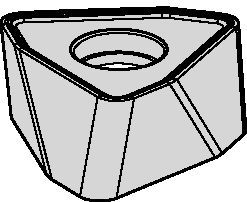
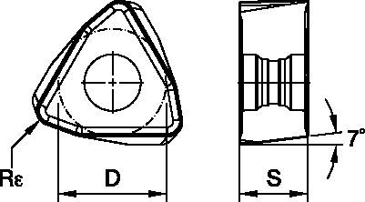
Inserts for KenFeed™ 2X • WOEJ09-HD
KenFeed™ 2X Series
Features and benefits
- Double-sided insert with six cutting edges.
- Unique and strong insert design that enables high-feed conditions, up to 0,1 IPT.
- -HD geometry is the first choice for steels, high-strength steels, and cast iron.
| Material Group | Light | General | Heavy | |||
| – | (Light geometry) | – | (Strong geometry) | |||
| – | wear |  | toughness | |||
| – | Geometry | Grade | Geometry | Grade | Geometry | Grade |
| P1–P2 | .S..GD | KCPK30 | .S..GD | KCPM40 | .S..HD | KCPM40 |
| P3–P4 | .S..GD | KCPK30 | .S..GD | KCPM40 | .S..HD | KCPM40 |
| P5–P6 | .S..GD | KCPK30 | .S..GD | KC725M | .S..HD | KC725M |
| M1–M2 | .S..GD | KC522M | .S..GD | KC725M | .S..HD | KC725M |
| M3 | .S..GD | KCPK30 | .S..GD | KCPM40 | .S..HD | KCPM40 |
| K1–K2 | .S..HD | KCK15 | .S..HD | KCK15 | .S..HD | KCK15 |
| K3 | .S..GD | KCPK30 | .S..HD | KCK15 | .S..HD | KCPK30 |
| N1–N2 | – | – | – | – | – | – |
| N3 | – | – | – | – | – | – |
| S1–S2 | .S..GD | KC522M | .S..GD | KC725M | .S..HD | KC725M |
| S3 | .S..GD | KC725M | .S..GD | KCPM40 | .S..HD | KCPM40 |
| S4 | .S..GD | KC522M | .S..HD | KC522M | .S..HD | KC725M |
| H1 | – | – | – | – | – | – |
Insert Selection Guide
| Material Group | Light | General | Heavy | |||
| (Light geometry) | (Strong geometry) | |||||
| wear | | toughness | ||||
| Geometry | Grade | Geometry | Grade | Geometry | Grade | |
| P1–P2 | .S..GD | KCPK30 | .S..GD | KCPM40 | .S..HD | KCPM40 |
| P3–P4 | .S..GD | KCPK30 | .S..GD | KCPM40 | .S..HD | KCPM40 |
| P5–P6 | .S..GD | KCPK30 | .S..GD | KC725M | .S..HD | KC725M |
| M1–M2 | .S..GD | KC522M | .S..GD | KC725M | .S..HD | KC725M |
| M3 | .S..GD | KCPK30 | .S..GD | KCPM40 | .S..HD | KCPM40 |
| K1–K2 | .S..HD | KCK15 | .S..HD | KCK15 | .S..HD | KCK15 |
| K3 | .S..GD | KCPK30 | .S..HD | KCK15 | .S..HD | KCPK30 |
| N1–N2 | – | – | – | – | – | – |
| N3 | – | – | – | – | – | – |
| S1–S2 | .S..GD | KC522M | .S..GD | KC725M | .S..HD | KC725M |
| S3 | .S..GD | KC725M | .S..GD | KCPM40 | .S..HD | KCPM40 |
| S4 | .S..GD | KC522M | .S..HD | KC522M | .S..HD | KC725M |
| H1 | – | – | – | – | – | – |
Recommended Starting Feeds [mm]
| Insert Geometry | Recommended Starting Feed per Tooth (Fz) in Relation to % of Radial Engagement (ae) | Insert Geometry | ||||||||||||||
| 5% | 10% | 20% | 30% | 40–100% | ||||||||||||
| .S..GD | 1,15 | 2,42 | 3,84 | 0,82 | 1,71 | 2,67 | 0,61 | 1,26 | 1,96 | 0,53 | 1,10 | 1,70 | 0,49 | 1,01 | 1,55 | .S..GD |
| .S..HD | 1,15 | 2,78 | 4,27 | 0,82 | 1,96 | 2,94 | 0,61 | 1,44 | 2,16 | 0,53 | 1,26 | 1,87 | 0,49 | 1,15 | 1,71 | .S..HD |
| Light | General | Heavy |
Recommended Starting Feeds [IPT]
| Light | General | Heavy |
| Insert Geometry | Recommended Starting Feed per Tooth (Fz) in Relation to % of Radial Engagement (ae) | Insert Geometry | ||||||||||||||
| 5% | 10% | 20% | 30% | 40–100% | ||||||||||||
| .S..GD | .045 | .089 | .141 | .032 | .063 | .098 | .024 | .047 | .072 | .021 | .040 | .063 | .019 | .037 | .057 | .S..GD |
| .S..HD | .045 | .109 | .168 | .032 | .077 | .116 | .024 | .057 | .085 | .021 | .049 | .074 | .019 | .045 | .067 | .S..HD |
Recommended Starting Speeds [m/min]
| Material Group | KC522M | KC725M | KCK15 | KCPK30 | |||||||||
| P | 1 | 395 | 345 | 325 | 315 | 275 | 255 | – | – | – | 545 | 475 | 440 |
| 2 | 330 | 290 | 240 | 260 | 230 | 195 | – | – | – | 335 | 305 | 275 | |
| 3 | 305 | 255 | 215 | 240 | 205 | 170 | – | – | – | 305 | 275 | 250 | |
| 4 | 270 | 225 | 180 | 215 | 180 | 145 | – | – | – | 225 | 210 | 190 | |
| 5 | 225 | 200 | 180 | 180 | 160 | 145 | – | – | – | 310 | 275 | 255 | |
| 6 | 200 | 150 | 120 | 160 | 120 | 95 | – | – | – | 190 | 165 | – | |
| M | 1 | 245 | 215 | 200 | 205 | 180 | 165 | – | – | – | 250 | 220 | 190 |
| 2 | 225 | 190 | 160 | 185 | 160 | 130 | – | – | – | 225 | 195 | 170 | |
| 3 | 170 | 145 | 115 | 140 | 120 | 95 | – | – | – | 175 | 160 | 140 | |
| K | 1 | 275 | 250 | 220 | – | – | – | 505 | 460 | 410 | 355 | 320 | 285 |
| 2 | 215 | 195 | 180 | – | – | – | 400 | 355 | 330 | 280 | 255 | 230 | |
| 3 | 180 | 160 | 145 | – | – | – | 335 | 300 | 275 | 235 | 210 | 195 | |
| N | 1 | – | – | – | – | – | – | – | – | – | – | – | – |
| 2 | – | – | – | – | – | – | – | – | – | – | – | – | |
| S | 1 | 50 | 45 | 35 | 45 | 35 | 30 | – | – | – | – | – | – |
| 2 | 50 | 45 | 35 | 45 | 35 | 30 | – | – | – | – | – | – | |
| 3 | 60 | 50 | 35 | 55 | 45 | 30 | – | – | – | – | – | – | |
| 4 | 85 | 60 | 45 | 75 | 55 | 35 | – | – | – | – | – | – | |
| H | 1 | 145 | 110 | 85 | – | – | – | – | – | – | – | – | – |
| 2 | – | – | – | – | – | – | – | – | – | – | – | – | |
| 3 | – | – | – | – | – | – | – | – | – | – | – | – | |
Maximum Linear Ramping and Helical Interpolation from Solid • Inch
| cutter type | catalog number | recommended ramping angle (for continuous ramping process) | max ramp angle when Ap max (not for continuous ramping process) | max ramp angle for 360° helical interpolation | min hole diameter (DH min) | max flat-bottom hole diameter (DH1 max) | max diameter (no flat bottom) |
| Screw-On | KF2X100W0902M12L138 | 3.5° | 5.2° | 3.1° | 1.291 | 1.35 | 2.0 |
| KF2X125W0902M16L169 | 1.9° | 2.8° | 1.7° | 1.813 | 1.87 | 2.5 | |
| KF2X125W0903M16L169 | 1.9° | 2.8° | 1.7° | 1.813 | 1.87 | 2.5 | |
| KF2X150W0903M16L169 | 1.4° | 2.1° | 1.2° | 2.310 | 2.37 | 3.0 | |
| KF2X150W0904M16L169 | 1.4° | 2.1° | 1.2° | 2.310 | 2.37 | 3.0 | |
| End Mills | KF2X100W0902C100L600 | 3.5° | 5.2° | 3.1° | 1.291 | 1.35 | 2.0 |
| KF2X100W0902C100L800 | 3.5° | 5.2° | 3.1° | 1.291 | 1.35 | 2.0 | |
| KF2X125W0903C125L600 | 1.9° | 2.8° | 1.7° | 1.813 | 1.87 | 2.5 | |
| KF2X125W0903C125L800 | 1.9° | 2.8° | 1.7° | 1.813 | 1.87 | 2.5 | |
| KF2X150W0903C125L600 | 1.4° | 2.1° | 1.2° | 2.310 | 2.37 | 3.0 | |
| KF2X150W0903C125L800 | 1.4° | 2.1° | 1.2° | 2.310 | 2.37 | 3.0 | |
| Face Mills | KF2X150W0904S050L157 | 1.4° | 2.1° | 1.2° | 2.310 | 2.37 | 3.0 |
| KF2X200W0905S075L157 | 1.0° | 1.4° | 0.8° | 3.307 | 3.37 | 4.0 | |
| KF2X200W0906S075L157 | 1.0° | 1.4° | 0.8° | 3.307 | 3.37 | 4.0 | |
| KF2X250W0906S075L175 | 0.7° | 1.1° | 0.6° | 4.305 | 4.36 | 5.0 | |
| KF2X300W0907S100L175 | 0.6° | 1.0° | 0.5° | 5.303 | 5.36 | 6.0 | |
| KF2X300W0907S125L200 | 0.6° | 1.0° | 0.5° | 5.303 | 5.36 | 6.0 |
General Programming Information for Applying KenFeed 2X • IC 09
| Rt | Wt | t |
| .110 | .312 | .045 |
Maximum Linear Ramping and Helical Interpolation from Solid
| cutter type | catalog number | recommended ramping angle (for continuous ramping process) | max ramp angle when Ap max (not for continuous ramping process) | max ramp angle for 360° helical interpolation | min hole diameter (DH min) | max flat-bottom hole diameter (DH1 max) | max diameter (no flat bottom) |
| Screw-On | KF2X2X25Z02M12WO09 | 3.6° | 5.4° | 3.1° | 26,5 | 33,7 | 50 |
| KF2X32Z03M16WO09 | 1.8° | 2.7° | 1.7° | 41,2 | 48,4 | 64 | |
| KF2X35Z03M16WO09 | 1.6° | 2.4° | 1.4° | 46,8 | 54,0 | 70 | |
| KF2X42Z04M16WO09 | 1.2° | 1.9° | 0.8° | 68,7 | 75,9 | 84 | |
| End Mills | KF2X25Z02A25WO09L140 | 3.6° | 5.4° | 3.1° | 26,5 | 33,7 | 50 |
| KF2X25Z02A25WO09L200 | 3.6° | 5.4° | 3.1° | 26,5 | 33,7 | 50 | |
| KF2X25Z02A25WO09L300 | 3.6° | 5.4° | 3.1° | 26,5 | 33,7 | 50 | |
| KF2X28Z02A25WO09L200 | 3.1° | 4.6° | 2.5° | 31,6 | 38,8 | 56 | |
| KF2X32Z03A32WO09L150 | 1.8° | 2.7° | 1.7° | 41,2 | 48,4 | 64 | |
| KF2X32Z03A32WO09L200 | 1.8° | 2.7° | 1.7° | 41,2 | 48,4 | 64 | |
| KF2X32Z03A32WO09L300 | 1.8° | 2.7° | 1.7° | 41,2 | 48,4 | 64 | |
| KF2X35Z03A32WO09L200 | 1.6° | 2.4° | 1.4° | 46,8 | 54,0 | 70 | |
| Face Mills | KF2X40Z04WO09 | 1.3° | 2.0° | 1.2° | 56,4 | 63,6 | 80 |
| KF2X50Z05WO09 | 1.0° | 1.5° | 0.8° | 76,7 | 83,9 | 100 | |
| KF2X52Z05WO09 | 1.0° | 1.4° | 0.8° | 80,7 | 87,9 | 104 | |
| KF2X63Z05S22WO09 | 0.8° | 1.2° | 0.6° | 102,7 | 109,9 | 126 | |
| KF2X63Z05WO09 | 0.8° | 1.2° | 0.6° | 102,7 | 109,9 | 126 | |
| KF2X66Z06S22WO09 | 0.7° | 1.1° | 0.5° | 108,7 | 115,9 | 132 | |
| KF2X66Z06WO09 | 0.7° | 1.1° | 0.5° | 108,7 | 115,9 | 132 | |
| KF2X80Z07WO09 | 0.6° | 0.9° | 0.4° | 136,6 | 143,8 | 160 |
Maximum Linear Ramping and Helical Interpolation from Solid
| diameter | max ramp angle | max ramp angle for 360° helical interpolation | max plunge depth | min hole diameter (DH min) | max flat-bottom hole diameter (DH1 max) | max diameter (no flat bottom) |
| 1.50 | 5.5° | 1.93° | 0.076 | 1.90 | 2.22 | 3.00 |
| 2.00 | 4.4° | 1.18° | 0.076 | 2.86 | 3.22 | 4.00 |
| 2.50 | 3.0° | 0.85° | 0.076 | 3.85 | 4.22 | 5.00 |
| 3.00 | 2.3° | 0.67° | 0.076 | 4.84 | 5.21 | 6.00 |
| 4.00 | 1.6° | 0.47° | 0.076 | 6.84 | 7.21 | 8.00 |
| 5.00 | 1.2° | 0.36° | 0.076 | 8.84 | 9.21 | 10.00 |