Welcome
Please confirm your preferences
Update Preferences
Product Suggestions
Product Family suggestions
Hi, User Name
Your Selected Account:
There is an issue with your account. Please contact customer support.
Sold To Account Change Account
Ship To Account Change Account
- Dashboard
- Manage Orders
- Manage Channels
- Address Book
Notifications
Mark all as read- Change Password
- My Profile
- Sign Out
Item(s) successfully added to cart
View Cart
View Cart
Take your shop to the next level. See Promotions
Item(s) successfully added to cart
View Cart
View Cart
Editing Solution
Adding Solution
Solution Name:{{SolutionName}}- Products
- /
- Metalworking Tools
- /
- Milling
- /
- Solid Carbide End Milling
- /
- High-Performance Solid Carbide End Mills
- /
- HARVI IV™ High-Performance Solid Carbide End Mills
- /
- HARVI™ IV • Radiused • 8 Flutes • Internal Coolant • Chipbreaker • Plain Shank • Inch
Product Similar To: [Product Name]
Sending to {{cadTool}} in progress...
Downloaded file will be available after import in the {{cadTool}} tool library.
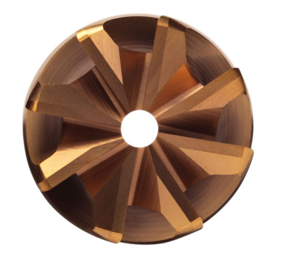
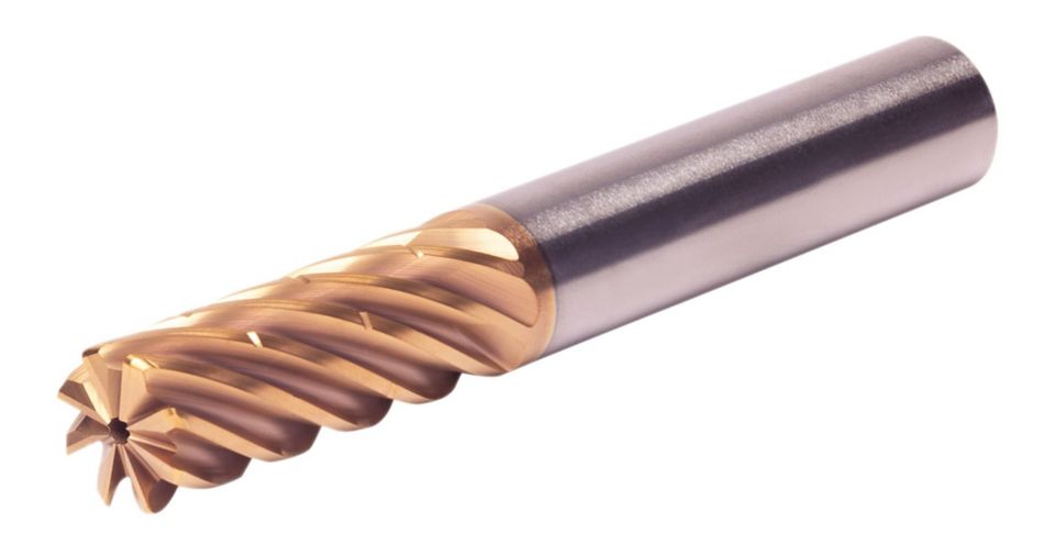
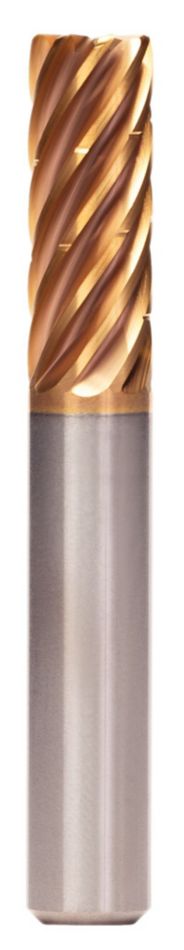
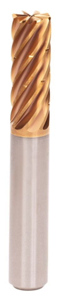
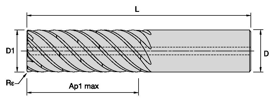
HARVI™ IV • Radiused • 8 Flutes • Internal Coolant • Chipbreaker • Plain Shank • Inch
HARVI™ IV Eight Flute End Mill for Roughing and Finishing
Covering the Broadest Range of Applications and Materials
Features and benefits
- Single tool for roughing and finishing to reduce tool setups.
- Proprietary core and flute design with optimum flute spacing for perfect chip formation and highest tool rigidity.
- Developed for highest productivity in titanium, high-temperature alloys, and stainless steels.
- With chip breakers for optimized chip evacuation.
Uses and application
Trochoidal Milling
100665610
107038547
Helical Milling
Ramping: Blank
Side Milling/Shoulder Milling: Square End
Pocketing
| Angle of engagement (phi°) relative to cutting width (Ae) |  | |||||||||
| ae | 2% | 5% | 7.50% | 10% | 15% | 20% | 30% | 40% | 50% | 100% |
| phi - angle of engagement | 16.26 | 25.84 | 31.79 | 36.87 | 45.57 | 53.13 | 66.42 | 78.46 | 90 | 180 |
| Adjustment factors for speed (Vc) and feed (Fz) • METRIC | |||||||
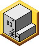
| Maximum cutting width (Ae) for given cutting depth (Ap) | |||||||
| Ap | ≤.125 x D1 | >.125xD1 ≤ .5xD1 | >.5xD1 ≤ 1xD1 | >1xD1 ≤ 2xD1 | >2xD1 ≤ 3xD1 | >3xD1 ≤ 4xD1 | >4 x D1 |
| Max Ae | 100% x D1 | 50% x D1 x KAp | 40% x D1 x KAp | 30% x D1 x KAp | 20% x D1 x KAp | 15% x D1 x KAp | 10% x D1 x KAp |
| Note: KAp value is given on the Speed and Feed table, according to the type of workpiece material selected. | |||||||
| Adjustment factors for speed (Vc) and feed (Fz) • METRIC | ||||||||||
| Ae/D1 | ≤2% | >2% ≤ 5% | >5 ≤ 7.5% | >7.5% ≤ 10% | >10% ≤ 15% | >15% ≤ 20% | >20% ≤ 30% | >30% ≤ 40% | >40% ≤ 50% | >50% ≤ 100% |
| Kv | 3 | 2.5 | 1.9 | 1.4 | 1.35 | 1.3 | 1.2 | 1.1 | 1 | 0.9 |
| KFz | 3.28 | 2.3 | 1.95 | 1.7 | 1.5 | 1.25 | 1.09 | 1.02 | 1 | 1 |
| Note: Identify the radial engagement per percentage of the tool diameter (Ae/D1). That column will give you the factor to multiply the Base SMF and Base IPT on the Speed and Feed original table Kv = Factor to multiply the Speed by KFz = Factor to multiply the Feed by | ||||||||||
| To calculate application specific cutting data, please use KAp, Kv, and Kfz from tables above for adaption of cutting speeds and feeds respectively: Maximum Ae=(Ap1Max/D1) * KAp * D1 Vc new = Vc * Kv IPT new = IPT * KFz | Sample Calculation Material: S4 D1: 25 mm Ap: 2xD1 Max Ae: 30% x KAp x D1 --- 30% * 0.7 * D1 = 21%xD1 SFM: Base x Kv --- 45 * 1.2 = 54 IPT: Base x KFz --- 0.081 * 1.09 = 0.088 | Final cutting data recommendation: Max Ae = 0.3 * 0.7 * 25 = 5.25 mm Vc new = 45 * 1.2 = 54 m/min IPT new = 0.081 * 1.09 = 0.088 mm/th | ||||||||
| Table for Feed and Speed Calculation with Adjustment Factor • METRIC | ||||||||
 | Side Milling (A) | KCSM15A | Recommended feed per tooth (fz=mm/th) for side milling | |||||
| Material | Max Ae Factor (KAp) | Base Cutting Speed Vc (m/min) | 10 | 12 | 16 | 20 | 25 | |
| P | 3 | 1 | 130 | 0.049 | 0.055 | 0.067 | 0.080 | 0.095 |
| 4 | 1 | 100 | 0.044 | 0.049 | 0.059 | 0.069 | 0.081 | |
| 5 | 0.8 | 65 | 0.038 | 0.043 | 0.053 | 0.063 | 0.076 | |
| 6 | 0.7 | 50 | 0.032 | 0.036 | 0.043 | 0.050 | 0.060 | |
| M | 1 | 1 | 80 | 0.049 | 0.055 | 0.067 | 0.080 | 0.095 |
| 2 | 0.8 | 60 | 0.038 | 0.043 | 0.053 | 0.063 | 0.076 | |
| 3 | 0.8 | 60 | 0.032 | 0.036 | 0.043 | 0.050 | 0.060 | |
| S | 1 | 0.5 | 50 | 0.049 | 0.055 | 0.067 | 0.080 | 0.095 |
| 2 | 0.5 | 30 | 0.038 | 0.043 | 0.053 | 0.063 | 0.076 | |
| 3 | 0.5 | 25 | 0.026 | 0.030 | 0.036 | 0.043 | 0.051 | |
| 4 | 0.7 | 45 | 0.041 | 0.051 | 0.061 | 0.069 | 0.081 | |
| H | 1 | 0.8 | 80 | 0.044 | 0.049 | 0.059 | 0.069 | 0.081 |
| 2 | 0.5 | 70 | 0.037 | 0.041 | 0.050 | 0.059 | 0.070 | |
| These guidelines may require variations to achieve optimum results. Above parameters are based on ideal conditions. For smaller taper machining centers, please adjust parameters accordingly on | ||||||||
| Adjustment factors for speed (Vc) and feed (Fz) • INCH | ||||||||||
| Ae/D1 | ≤2% | >2% ≤ 5% | >5 ≤ 7.5% | >7.5% ≤ 10% | >10% ≤ 15% | >15% ≤ 20% | >20% ≤ 30% | >30% ≤ 40% | >40% ≤ 50% | >50% ≤ 100% |
| Kv | 3 | 2.5 | 1.9 | 1.4 | 1.35 | 1.3 | 1.2 | 1.1 | 1 | 0.9 |
| KFz | 3.28 | 2.3 | 1.95 | 1.7 | 1.5 | 1.25 | 1.09 | 1.02 | 1 | 1 |
| Note: Identify the radial engagement per percentage of the tool diameter (Ae/D1). That column will give you the factor to multiply the Base SMF and Base IPT on the Speed and Feed original table Kv = Factor to multiply the Speed by KFz = Factor to multiply the Feed by | ||||||||||
| To calculate application specific cutting data, please use KAp, Kv, and Kfz from tables above for adaption of cutting speeds and feeds respectively: Maximum Ae=(Ap1Max/D1) * KAp * D1 Vc new = Vc * Kv IPT new = IPT * KFz | Sample Calculation Material: S4 D1: 25 mm Ap: 2xD1 Max Ae: 30% x KAp x D1 --- 30% * 0.7 * D1 = 21%xD1 SFM: Base x Kv --- 45 * 1.2 = 54 IPT: Base x KFz --- 0.081 * 1.09 = 0.088 | Final cutting data recommendation: Max Ae = 0.3 * 0.7 * 25 = 5.25 mm Vc new = 45 * 1.2 = 54 m/min IPT new = 0.081 * 1.09 = 0.088 mm/th | ||||||||
| Table for Feed and Speed Calculation with Adjustment Factor • INCH | |||||||||
| Side Milling (A) | KCSM15A | Recommended feed per tooth (fz=IPT) for side milling | ||||||
| frac. | 3/8 | 1/2 | 5/8 | 3/4 | 1 | ||||
| Material | Max Ae Factor (KAp) | Base Cutting Speed Vc (SFM) | dec. | 0.375 | 0.500 | 0.625 | 0.750 | 1 | |
| P | 3 | 1 | 420 | IPT | 0.0018 | 0.0023 | 0.0027 | 0.003 | 0.0037 |
| 4 | 1 | 320 | IPT | 0.0016 | 0.0021 | 0.0024 | 0.0026 | 0.0031 | |
| 5 | 0.8 | 210 | IPT | 0.0014 | 0.0018 | 0.0022 | 0.0024 | 0.0029 | |
| 6 | 0.7 | 160 | IPT | 0.0012 | 0.0015 | 0.0018 | 0.0019 | 0.0022 | |
| M | 1 | 1 | 275 | IPT | 0.0018 | 0.0023 | 0.0027 | 0.003 | 0.0037 |
| 2 | 0.8 | 200 | IPT | 0.0014 | 0.0018 | 0.0022 | 0.0024 | 0.0029 | |
| 3 | 0.8 | 200 | IPT | 0.0012 | 0.0015 | 0.0018 | 0.0019 | 0.0022 | |
| S | 1 | 0.5 | 160 | IPT | 0.0018 | 0.0023 | 0.0027 | 0.003 | 0.0037 |
| 2 | 0.5 | 100 | IPT | 0.0014 | 0.0018 | 0.0022 | 0.0024 | 0.0029 | |
| 3 | 0.5 | 80 | IPT | 0.001 | 0.0013 | 0.0014 | 0.0016 | 0.002 | |
| 4 | 0.7 | 160 | IPT | 0.0016 | 0.002 | 0.0024 | 0.0027 | 0.0032 | |
| H | 1 | 0.8 | 260 | IPT | 0.0016 | 0.0021 | 0.0024 | 0.0026 | 0.0031 |
| 2 | 0.5 | 230 | IPT | 0.0014 | 0.0018 | 0.002 | 0.0022 | 0.0026 | |
| These guidelines may require variations to achieve optimum results. Above parameters are based on ideal conditions. For smaller taper machining centers, please adjust parameters accordingly on | |||||||||
| Adjustment factors for speed (Vc) and feed (Fz) • INCH | |||||||
| Maximum cutting width (Ae) for given cutting depth (Ap) | |||||||
| Ap | ≤.125 x D1 | >.125xD1 ≤ .5xD1 | >.5xD1 ≤ 1xD1 | >1xD1 ≤ 2xD1 | >2xD1 ≤ 3xD1 | >3xD1 ≤ 4xD1 | >4 x D1 |
| Max Ae | 100% x D1 | 50% x D1 x KAp | 40% x D1 x KAp | 30% x D1 x KAp | 20% x D1 x KAp | 15% x D1 x KAp | 10% x D1 x KAp |
| Note: KAp value is given on the Speed and Feed table, according to the type of workpiece material selected. | |||||||