Product Similar To:
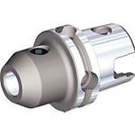
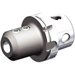
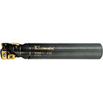
KDMR • Cylindrical Shank • Long Shank • Metric
Multifunctional Cutter
Material Number3587082
ISO Catalog IDKDMR50S40140WLANSI Catalog IDKDMR50S40140WL
- P Steel
- M Stainless Steel
Drilling
Helical Milling
Plunge Milling
Ramping: Blank
Slotting: Ball Nose
Shank - Cylindrical Plain
Pocketing
Sending to {{cadTool}} in progress...
Downloaded file will be available after import in the {{cadTool}} tool library.
- Overview
- Application Data
- Downloads
- Compatible Parts Machine Side
- Compatible Parts Workpiece Side
- Spare Parts
- Reviews
- Q&A
| Material Number | 3587082 |
| ISO Catalog ID | KDMR50S40140WL |
| ANSI Catalog ID | KDMR50S40140WL |
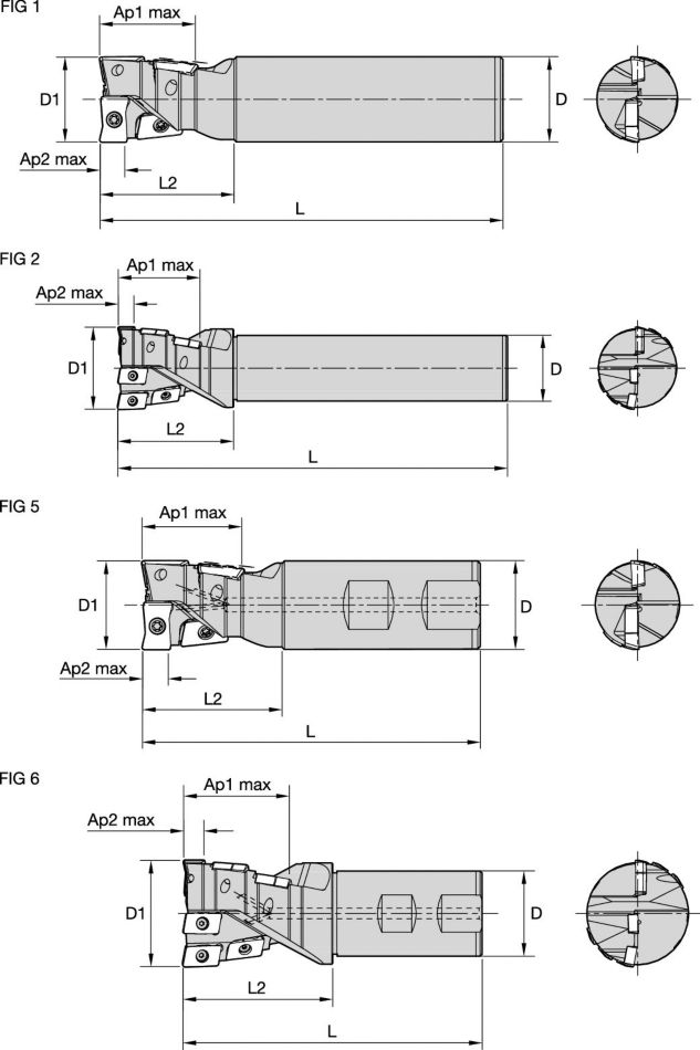
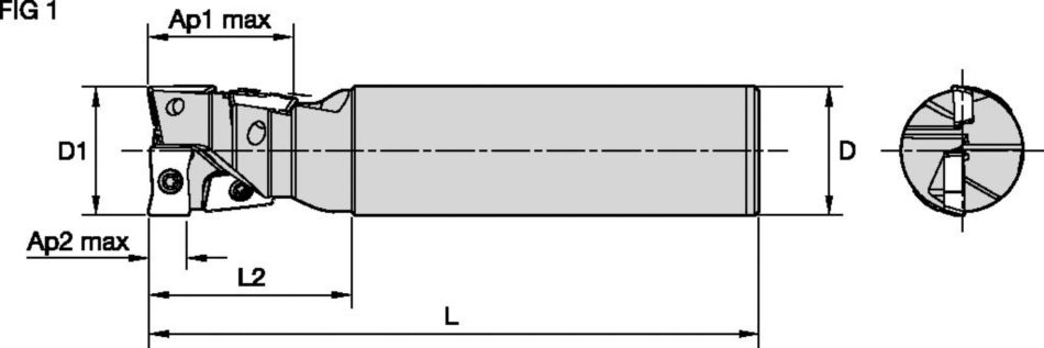
| [D1] Effective Cutting Diameter | 50 mm |
| [D1] Effective Cutting Diameter | 1.9685 in |
| [D] Adapter / Shank / Bore Diameter | 40 mm |
| [D] Adapter / Shank / Bore Diameter | 1.5748 in |
| [L] Overall Length | 140 mm |
| [L] Overall Length | 5.5118 in |
| [L1] Gage Length | 140 mm |
| [L1] Gage Length | 5.5118 in |
| [L2] Head Length | 70 mm |
| [L2] Head Length | 2.7559 in |
| [AP1MAX] 1st Maximum Cutting Depth | 54 mm |
| [AP1MAX] 1st Maximum Cutting Depth | 2.126 in |
| [AP2MAX] 2nd Maximum Cutting Depth | 9.5 mm |
| [AP2MAX] 2nd Maximum Cutting Depth | 0.374 in |
| Number of Inserts | 7 |
| [Z] Number of Flutes | 2 |
| Coolant Supply | N |
| KYC_CTLG_REF_ILLUS_NUM | FIG 6 |
| Weight Kilograms | 1.43 |
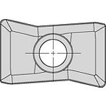
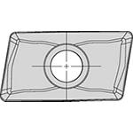
| Gage Insert | GOMT160408ERLD |
| Gage Insert | JOMT160408ERLF |
Workpiece Materials
- Steel
- Stainless Steel
Uses and application
Drilling
Helical Milling
Plunge Milling
Ramping: Blank
Slotting: Ball Nose
Shank - Cylindrical Plain
Pocketing
Features and benefits
- Low cutting forces.
- Reduced shank diameters for access down long side walls.
- Excellent chip evacuation, even machining on an angle.
- When drilling, use (1) as the effective number of teeth (ZU).
- Milling to the maximum axial depth of (Ap2), we have (2) effective teeth.
Create Solution to calculate Feeds and Speeds
After creating a solution just choose the Feeds & Speeds icon and our system will provide recommendations. You can customize the information by adding your machine and specifications or make adjustments using the sliders.
Feeds
Recommended Starting Feeds [mm]
| Insert Geometry | Recommended Starting Feed per Tooth (Fz) in Relation to % of Radial Engagement (ae) | Insert Geometry | ||||||||||||||
| 10% | 20% | 30% | 40% | 50–100% | ||||||||||||
| .LD/.LF | 0,14 | 0,34 | 0,51 | 0,11 | 0,25 | 0,38 | 0,09 | 0,22 | 0,33 | 0,09 | 0,21 | 0,31 | 0,08 | 0,20 | 0,30 | .LD/.LF |
| Light | General | Heavy |
Recommended Starting Feeds [IPT]
| Insert Geometry | Recommended Starting Feed per Tooth (Fz) in Relation to % of Radial Engagement (ae) | Insert Geometry | ||||||||||||||
| 10% | 20% | 30% | 40% | 50–100% | ||||||||||||
| .LD/.LF | .006 | .014 | .020 | .004 | .010 | .015 | .004 | .009 | .013 | .003 | .008 | .012 | .003 | .008 | .012 | .LD/.LF |
| Light | General | Heavy |
Speeds
Recommended Starting Speeds [m/min]
| Material Group | KC505M | KC720M | |||||
| P | 1 | – | – | – | 260 | 240 | 215 |
| 2 | – | – | – | 240 | 215 | 190 | |
| 3 | – | – | – | 215 | 190 | 170 | |
| 4 | 360 | 260 | 215 | 190 | 180 | 170 | |
| 5 | 360 | 260 | 215 | 170 | 145 | 120 | |
| 6 | 350 | 240 | 190 | 120 | 95 | 95 | |
| M | 1 | – | – | – | 240 | 215 | 190 |
| 2 | – | – | – | 190 | 170 | 145 | |
| 3 | – | – | – | 145 | 120 | 95 | |
| K | 1 | 190 | 170 | 150 | – | – | – |
| 2 | 175 | 155 | 135 | – | – | – | |
| 3 | 115 | 95 | 75 | – | – | – | |
| N | 1–2 | – | – | – | – | – | – |
| 3 | – | – | – | – | – | – | |
| S | 1 | – | – | – | – | – | – |
| 2 | – | – | – | – | – | – | |
| 3 | – | – | – | – | – | – | |
| 4 | – | – | – | – | – | – | |
| H | 1 | – | – | – | – | – | – |
Recommended Starting Speeds [SFM]
| Material Group | KC505M | KC720M | |||||
| P | 1 | – | – | – | 860 | 790 | 710 |
| 2 | – | – | – | 790 | 710 | 630 | |
| 3 | – | – | – | 710 | 630 | 550 | |
| 4 | 1180 | 860 | 710 | 630 | 590 | 550 | |
| 5 | 1180 | 860 | 710 | 550 | 470 | 400 | |
| 6 | 1140 | 780 | 620 | 400 | 310 | 310 | |
| M | 1 | – | – | – | 780 | 710 | 630 |
| 2 | – | – | – | 630 | 550 | 470 | |
| 3 | – | – | – | 470 | 400 | 310 | |
| K | 1 | – | – | – | – | – | – |
| 2 | – | – | – | – | – | – | |
| 3 | – | – | – | – | – | – | |
| N | 1–2 | – | – | – | – | – | – |
| 3 | – | – | – | – | – | – | |
| S | 1 | – | – | – | – | – | – |
| 2 | – | – | – | – | – | – | |
| 3 | – | – | – | – | – | – | |
| 4 | – | – | – | – | – | – | |
| H | 1 | – | – | – | – | – | – |
Insert Selection
| Material Group | Light | General | Heavy | |||
| – | (Light geometry) | – | (Strong geometry) | |||
| – | wear |  | toughness | |||
| – | Geometry | Grade | Geometry | Grade | Geometry | Grade |
| P1–P2 | .LD/.LF | KC720M | .LD/.LF | KC720M | .LD/.LF | KC720M |
| P3–P4 | .LD/.LF | KC720M | .LD/.LF | KC720M | .LD/.LF | KC720M |
| P5–P6 | .LD/.LF | KC720M | .LD/.LF | KC720M | .LD/.LF | KC720M |
| M1–M2 | .LD/.LF | KC720M | .LD/.LF | KC720M | .LD/.LF | KC720M |
| M3 | .LD/.LF | KC720M | .LD/.LF | KC720M | .LD/.LF | KC720M |
| K1–K2 | .LD/.LF | KC505M | .LD/.LF | KC505M | .LD/.LF | KC505M |
| K3 | .LD/.LF | KC505M | .LD/.LF | KC505M | .LD/.LF | KC505M |
| N1–N2 | – | – | – | – | – | – |
| N3 | – | – | – | – | – | – |
| S1–S2 | – | – | – | – | – | – |
| S3 | – | – | – | – | – | – |
| S4 | – | – | – | – | – | – |
| H1 | – | – | – | – | – | – |
TechnicalInfo
Drilling
| drilling | |
| cutting diameter | maximum depth (mm) |
| Ø 16 | 13 |
| Ø 17 | 13 |
| Ø 20 | 17 |
| Ø 21 | 17 |
| Ø 25 | 22 |
| Ø 26 | 22 |
| Ø 32 | 25 |
| Ø 33 | 25 |
| Ø 40 | 25 |
| Ø 50 | 25 |
Drilled Hole Bottom Shape
| Drilled Hole Bottom Shape | ||||||
| cutting diameter | Ø 16, Ø 17 | Ø 20, Ø 21 | Ø 25, Ø 26 | Ø 32, Ø 33 | Ø 40 | Ø 50 |
| A (mm) | 0,50 | 0,64 | 0,85 | 1,12 | 1,54 | 1,65 |
Ramping
| end mill | applicable insert for each cutter diameter | |||
| D1 | side Insert | quantity | center | quantity |
| Ø 16 | JOMT08T208ERLF | 3 | GOMT08T208ERLD | 1 |
| Ø 17 | JOMT08T208ERLF | 3 | GOMT08T208ERLD | 1 |
| Ø 20 | JOMT100308ERLF | 3 | GOMT100308ERLD | 1 |
| Ø 21 | JOMT100308ERLF | 3 | GOMT100308ERLD | 1 |
| Ø 25 | JOMT13T308ERLF | 3 | GOMT13T308ERLD | 1 |
| Ø 26 | JOMT13T308ERLF | 3 | GOMT13T308ERLD | 1 |
| Ø 32 | JOMT160408ERLF | 3 | GOMT160408ERLD | 1 |
| Ø 33 | JOMT160408ERLF | 3 | GOMT160408ERLD | 1 |
| Ø 40 | JOMT13T308ERLF | 6 | GOMT13T308ERLD | 1 |
| Ø 50 | JOMT160408ERLF | 6 | GOMT160408ERLD | 1 |
I have read and accepted the Terms & Conditions of use

