List Price
/each
Discount
Your Price
/each
Sold in pkg. of 0Adjusted to meet the minimum package size.
Minimum qty: 0Adjusted to meet the minimum quantity requirement.
In StockThis item is no longer availableLonger Delivery


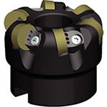
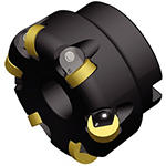

 Milling - Pressurized Air Coolant
 Face Milling
 Side Milling/Shoulder Milling: Ball Nose
 Milling - Side and Face
Downloaded file will be available after import in the {{cadTool}} tool library.
| Material Number | 5703938 |
| ISO Catalog ID | KCRA250RN4306S075L175 |
| ANSI Catalog ID | KCRA250RN4306S075L175 |
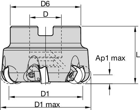
| [D1MAX] Maximum Cutting Diameter | 63.5 mm |
| [D1MAX] Maximum Cutting Diameter | 2.5 in |
| [D1] Effective Cutting Diameter | 50.8 mm |
| [D1] Effective Cutting Diameter | 2 in |
| [D] Adapter / Shank / Bore Diameter | 19.05 mm |
| [D] Adapter / Shank / Bore Diameter | .75 in |
| [D6] Hub Diameter | 44.45 mm |
| [D6] Hub Diameter | 1.75 in |
| [L] Overall Length | 44.45 mm |
| [L] Overall Length | 1.75 in |
| [AP1MAX] 1st Maximum Cutting Depth | 6.35 mm |
| [AP1MAX] 1st Maximum Cutting Depth | .25 in |
| Number of Inserts | 6 |
| Max RPM | 20300 |
| Weight Pounds | 1.39 |
| Gage Insert | RNGN120400 |
Milling - Pressurized Air CoolantFace MillingSide Milling/Shoulder Milling: Ball NoseMilling - Side and FaceCreate Solution to calculate Feeds and Speeds
After creating a solution just choose the Feeds & Speeds icon and our system will provide recommendations. You can customize the information by adding your machine and specifications or make adjustments using the sliders.
| Material Group | Light | General | Heavy | |||
| – | (Light geometry) | – | (Strong geometry) | |||
| – | wear |  | toughness | |||
| – | Geometry | Grade | Geometry | Grade | Geometry | Grade |
| P1–P2 | – | – | – | – | – | – |
| P3–P4 | – | – | – | – | – | – |
| P5–P6 | – | – | – | – | – | – |
| M1–M2 | – | – | – | – | – | – |
| M3 | – | – | – | – | – | – |
| K1–K2 | – | – | – | – | – | – |
| K3 | – | – | – | – | – | – |
| N1–N2 | – | – | – | – | – | – |
| N3 | – | – | – | – | – | – |
| S1–S2 | .EGN | KYS30 | .EGN | KYS30 | .TGN | KYS30 |
| S3 | .EGN | KYSP30 | .EGN | KYSP30 | .TGN | KYSP30 |
| S4 | – | – | – | – | – | – |
| H1 | – | – | – | – | – | – |
| Insert Geometry | Recommended Starting Feed per Tooth (Fz) in Relation to % of Radial Engagement (ae) | Insert Geometry | ||||||||||||||
| 10% | 20% | 30% | 40% | 50–100% | ||||||||||||
| .EGN | .003 | .004 | .005 | .003 | .003 | .003 | .002 | .002 | .003 | .002 | .002 | .003 | .002 | .002 | .003 | .EGN |
| .TGN | .005 | .007 | .008 | .004 | .005 | .006 | .003 | .004 | .005 | .003 | .004 | .005 | .003 | .004 | .005 | .TGN |
| Light | General | Heavy |
| Insert Geometry | Recommended Starting Feed per Tooth (Fz) in Relation to % of Radial Engagement (ae) | Insert Geometry | ||||||||||||||
| 10% | 20% | 30% | 40% | 50–100% | ||||||||||||
| .EGN | .004 | .004 | .005 | .003 | .003 | .004 | .003 | .003 | .003 | .002 | .003 | .003 | .002 | .003 | .003 | .EGN |
| .TGN | .006 | .008 | .009 | .004 | .006 | .007 | .004 | .005 | .006 | .004 | .005 | .005 | .003 | .005 | .005 | .TGN |
| Insert Geometry | Recommended Starting Feed per Tooth (Fz) in Relation to % of Radial Engagement (ae) | Insert Geometry | ||||||||||||||
| 10% | 20% | 30% | 40% | 50–100% | ||||||||||||
| .EGN | .007 | .008 | .009 | .005 | .006 | .007 | .005 | .005 | .006 | .004 | .005 | .006 | .004 | .005 | .006 | .EGN |
| .TGN | .010 | .014 | .016 | .008 | .010 | .012 | .007 | .009 | .010 | .006 | .008 | .010 | .006 | .008 | .010 | .TGN |
| Insert Geometry | Recommended Starting Feed per Tooth (Fz) in Relation to % of Radial Engagement (ae) | Insert Geometry | ||||||||||||||
| 10% | 20% | 30% | 40% | 50–100% | ||||||||||||
| .EGN | .005 | .006 | .007 | .004 | .004 | .005 | .003 | .004 | .004 | .003 | .003 | .004 | .003 | .003 | .004 | .EGN |
| .TGN | .008 | .010 | .012 | .006 | .008 | .009 | .005 | .007 | .008 | .005 | .006 | .007 | .005 | .006 | .007 | .TGN |
| Safety Notes | |||||
 |  |  |  |  |  |
| Read all instructions carefully | Wear eye protection | Inspect and tighten fasteners regularly | Warning: Cutting hazard | Warning: Hot surfaces | Do not exceed maximum RPM |
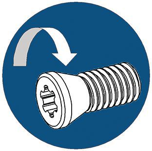
| Assembly Instructions | |
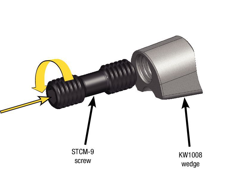
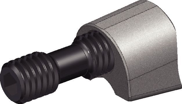
| Assemble STCM-25 screw to KW1008 wedge, 1 to 1 1/2 turns. | Wedge/screw assembly. |
 |  |
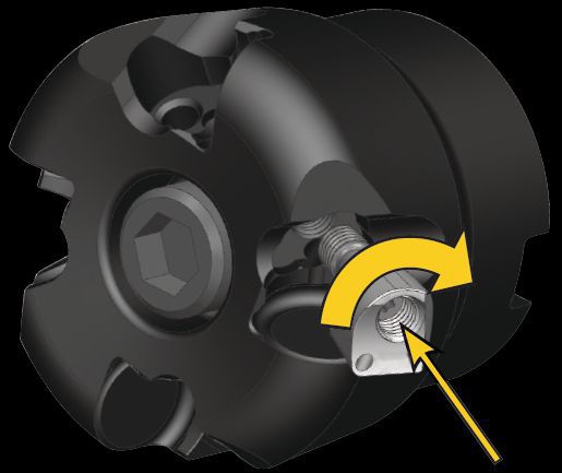
| Install wedge/screw assembly into cutter body, but maintain assembly gap for installing insert. | Slide insert, RNGN12... into pocket and torque wedge/insert assembly to 3,5 Nm (31 in/lbs). Repeat for each pocket. |
 | 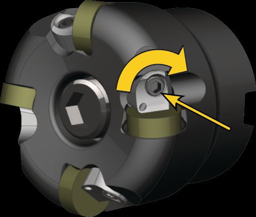 |
| Material Group | KYS30 | KYSP30 | |||||
| P | 1 | – | – | – | – | – | – |
| 2 | – | – | – | – | – | – | |
| 3 | – | – | – | – | – | – | |
| 4 | – | – | – | – | – | – | |
| 5 | – | – | – | – | – | – | |
| 6 | – | – | – | – | – | – | |
| M | 1 | – | – | – | – | – | – |
| 2 | – | – | – | – | – | – | |
| 3 | – | – | – | – | – | – | |
| K | 1 | – | – | – | – | – | – |
| 2 | – | – | – | – | – | – | |
| 3 | – | – | – | – | – | – | |
| N | 1 | – | – | – | – | – | – |
| 2 | – | – | – | – | – | – | |
| S | 1 | 2640 | 2160 | 1680 | 2640 | 2160 | 1680 |
| 2 | 2640 | 2160 | 1680 | 2640 | 2160 | 1680 | |
| 3 | 3840 | 3120 | 2400 | 3840 | 3120 | 2400 | |
| 4 | – | – | – | – | – | – | |
| H | 1 | – | – | – | – | – | – |
| 2 | – | – | – | – | – | – | |
| 3 | – | – | – | – | – | – | |
I have read and accepted the Terms & Conditions of use


ISO Catalog Number
ANSI Catalog Number
to find similar products.Please select a file to download
Models
Product data
. Please enter the desired qty for the material(s) you want to include in your promotion or Proceed Without Promotion and only your base materials will be added to the cart.
Minimum quantity should be
| SAP Material Number | ISO Catalog Number | Grade |
|---|
You are about to leave the Solution building process.
Are you sure you want to leave?