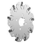
Produkt podobný k:
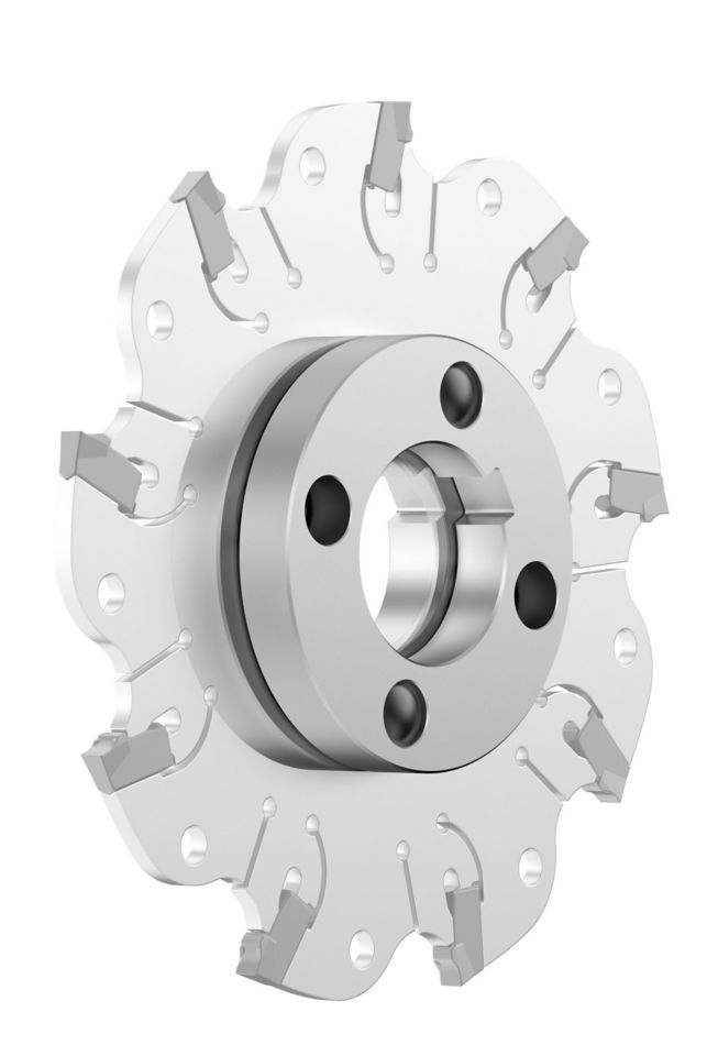
KVNS™ A2™ • Arbor Mount • Metric
Slot milling cutter for multiple materials
Objednací číslo1246150
ISO katalogové ID4.97164140ANSI katalogové ID4.97164140
- P Steel
- M Stainless Steel
- K Cast Iron
- N Non-Ferrous
- S High-Temp Alloys
Slotting: Side with AE/AP dimensions
Sending to {{cadTool}} in progress...
Downloaded file will be available after import in the {{cadTool}} tool library.
- Přehled
- Řezné podmínky
- Stahování
- Kompatibilní díly strana stroje
- Kompatibilní díly strana obrobku
- Náhradní díly
- Posouzení
- Otázky A Odpovědi
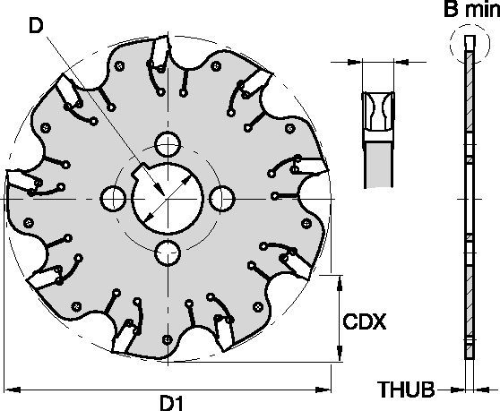
| Objednací číslo | 1246150 |
| ISO katalogové ID | 4.97164140 |
| ANSI katalogové ID | 4.97164140 |
| [BM] Cutting Width Minimum | 4 mm |
| [BM] Cutting Width Minimum | .1575 in |
| [D1] Effective Cutting Diameter | 160 mm |
| [D1] Effective Cutting Diameter | 6.299 in |
| [CDX] Radial Maximum Depth of Cut | 40 mm |
| [CDX] Radial Maximum Depth of Cut | 1.574 in |
| [D] Adapter / Shank / Bore Diameter | 40 mm |
| [D] Adapter / Shank / Bore Diameter | 1.574 in |
| [THUB] Hub Thickness | 3.4 mm |
| [THUB] Hub Thickness | .1339 in |
| Number of Inserts | 14 |
| Weight Kilograms | 0.41 |
| Gage Insert | 3.90040___ |
| Max RPM | 2000 |
Materiály obrobků
- Steel
- Stainless Steel
- Cast Iron
- Non-Ferrous
- High-Temp Alloys
Použití
Slotting: Side with AE/AP dimensions
Vlastnosti a výhody
- Self-clamping insert seat with fixed stop.
- Excellent for all flat-bottom slotting and cut-off operations.
- Two drive rings required for each cutter body. They must be ordered separately, and in pairs of two.
- For cutter diameters 200mm and 250mm support rings are optional (instead of drive rings). Support rings also must be ordered separately, and in pairs of two.
Vytvořit řešení pro výpočet posuvů a rychlosti
Po vytvoření řešení stačí vybrat ikonu Posuvy & Rychlosti a náš systém poskytne doporučení. Informace můžete upravit přidáním zařízení a specifikací nebo provést úpravy pomocí posuvníků.
Výběr břitové destičky
Výběr břitové destičky
| KVNS™ A2™ Slotting Cutters • Insert Selection Guide | ||||||
| Materiálová skupina | Lehké obrábění | Všeobecné použití | Těžké obrábění | |||
| – | (Lehká geometrie) | (Silná geometrie) | ||||
| – | Odolnost proti opotřebení |  | Houževnatost | |||
| – | Geometrie | Sorta | Geometrie | Sorta | Geometrie | Sorta |
| P1-P2 | .S..GD | KCPK30 | .S..GD | KCPK30 | .S..GB | KCPK30 |
| P3-P4 | .S..GD | KCPK30 | .S..GD | KCPK30 | .S..GB | KCPK30 |
| P5-P6 | .S..GD | KCPK30 | .S..GB | KCPK30 | .S..GB | KCPK30 |
| M1-M2 | .S..GD | KCPK30 | .S..GD | KCPK30 | .S..GB | KCPK30 |
| M3 | .S..GD | KCPK30 | .S..GB | KCPK30 | .S..GB | KCPK30 |
| K1-K2 | .S..GD | KCPK30 | .S..GD | KCPK30 | .S..GB | KCPK30 |
| K3 | .S..GD | KCPK30 | .S..GD | KCPK30 | .S..GB | KCPK30 |
| N1-N2 | – | – | – | – | – | – |
| N3 | – | – | – | – | – | – |
| S1-S2 | – | – | – | – | – | – |
| S3 | – | – | – | – | – | – |
| S4 | – | – | – | – | – | – |
| H1 | – | – | – | – | – | – |
Posuvy
Doporučené počáteční hodnoty posuvů [mm]
| KVNS™ A2™ Series • Recommended Starting Feeds [mm/th] | |||||||||||||||
| Geometrie břitových destiček | Doporučené počáteční posuvy na zub (Fz) podle % poměru radiální hloubky řezu (ae) | ||||||||||||||
| 5% | 10% | 20% | 30% | 40–100% | |||||||||||
| L | M | H | L | M | H | L | M | H | L | M | H | L | M | H | |
| .S..GD | 0,23 | 0,46 | 0,71 | 0,17 | 0,33 | 0,51 | 0,13 | 0,25 | 0,38 | 0,11 | 0,22 | 0,33 | 0,10 | 0,20 | 0,30 |
| .S..GB | 0,23 | 0,46 | 0,74 | 0,17 | 0,33 | 0,54 | 0,13 | 0,25 | 0,40 | 0,11 | 0,22 | 0,35 | 0,10 | 0,20 | 0,32 |
| L = Light Machining; M = Medium Machining; H = Heavy Machining NOTE: Use "Light Machining" values as starting feed rate. | |||||||||||||||
Recommended Starting Feeds [IPT]
| KVNS™ A2™ Series • Recommended Starting Feeds [IPT] | |||||||||||||||
| Geometrie břitových destiček | Doporučené počáteční posuvy na zub (Fz) podle % poměru radiální hloubky řezu (ae) | ||||||||||||||
| 5% | 10% | 20% | 30% | 40–100% | |||||||||||
| L | M | H | L | M | H | L | M | H | L | M | H | L | M | H | |
| .S..GD | 0.009 | 0.017 | 0.026 | 0.007 | 0.013 | 0.019 | 0.005 | 0.009 | 0.014 | 0.004 | 0.008 | 0.012 | 0.004 | 0.008 | 0.011 |
| .S..GB | 0.009 | 0.017 | 0.028 | 0.007 | 0.013 | 0.020 | 0.005 | 0.009 | 0.015 | 0.004 | 0.008 | 0.013 | 0.004 | 0.008 | 0.012 |
| L = Light Machining; M = Medium Machining; H = Heavy Machining NOTE: Use "Light Machining" values as starting feed rate. | |||||||||||||||
Rychlosti
Doporučené počáteční řezné rychlosti [m/min]
| KVNS™ A2™ Series • Recommended Starting Speed [m/min] | |||||||
| Sorta | KCPK30 | KMF | |||||
| Tloušťka třísky hex mm | Min | Max | Min | Max | |||
| Materiálová skupina | Max | Start | Min | Max | Start | Min | |
| P | 1 | 455 | 395 | 370 | – | – | – |
| 2 | 280 | 255 | 230 | – | – | – | |
| 3 | 255 | 230 | 205 | – | – | – | |
| 4 | 225 | 185 | 160 | – | – | – | |
| 5 | 190 | 170 | 150 | – | – | – | |
| 6 | 160 | 135 | 110 | – | – | – | |
| M | 1 | 205 | 185 | 155 | – | – | – |
| 2 | 185 | 160 | 140 | – | – | – | |
| 3 | 145 | 130 | 115 | – | – | – | |
| K | 1 | 295 | 265 | 240 | – | – | – |
| 2 | 235 | 210 | 190 | – | – | – | |
| 3 | 195 | 175 | 160 | – | – | – | |
| N | 1 | – | – | – | 335 | 298 | 271 |
| 2 | – | – | – | 335 | 298 | 271 | |
| 3 | – | – | – | 219 | 198 | 170 | |
| S | 1 | – | – | – | 30 | 24 | 20 |
| 2 | – | – | – | 30 | 24 | 20 | |
| 3 | – | – | – | 30 | 24 | 20 | |
| 4 | 50 | 45 | 35 | 24 | 24 | 24 | |
| H | 1 | – | – | – | – | – | – |
| Recommended Starting Speed are pointing to 90° Shoulder Milling . Starting Speed for Face and Copy Milling can be Increased by 20 %. As the average chip thickness increases, speed should be decreased. Material groups P, M, K and H show recommended starting speeds for dry machining. For wet machining, reduce speed by 20%. Material groups N and S show recommended starting speeds for wet machining. Not recommended for dry machining. | |||||||
Recommended Starting Speeds [SFM]
| KVNS™ A2™ Series • Recommended Starting Speed [SFM] | |||||||
| Sorta | KCPK30 | KMF | |||||
| Chip Thickness hex Inch | Min | Max | Min | Max | |||
| Materiálová skupina | Max | Start | Min | Max | Start | Min | |
| P | 1 | 1495 | 1295 | 1215 | – | – | – |
| 2 | 920 | 835 | 755 | – | – | – | |
| 3 | 835 | 755 | 675 | – | – | – | |
| 4 | 740 | 605 | 525 | – | – | – | |
| 5 | 625 | 560 | 490 | – | – | – | |
| 6 | 525 | 445 | 360 | – | – | – | |
| M | 1 | 675 | 605 | 510 | – | – | – |
| 2 | 605 | 525 | 460 | – | – | – | |
| 3 | 475 | 425 | 375 | – | – | – | |
| K | 1 | 970 | 870 | 785 | – | – | – |
| 2 | 770 | 690 | 625 | – | – | – | |
| 3 | 640 | 575 | 525 | – | – | – | |
| N | 1 | – | – | – | 1100 | 980 | 890 |
| 2 | – | – | – | 1100 | 980 | 890 | |
| 3 | – | – | – | 720 | 650 | 560 | |
| S | 1 | – | – | – | 100 | 80 | 65 |
| 2 | – | – | – | 100 | 80 | 65 | |
| 3 | – | – | – | 100 | 80 | 65 | |
| 4 | 165 | 150 | 115 | 80 | 80 | 80 | |
| H | 1 | – | – | – | – | – | – |
| Recommended Starting Speed are pointing to 90° Shoulder Milling . Starting Speed for Face and Copy Milling can be Increased by 20 %. As the average chip thickness increases, speed should be decreased. Material groups P, M, K and H show recommended starting speeds for dry machining. For wet machining, reduce speed by 20%. Material groups N and S show recommended starting speeds for wet machining. Not recommended for dry machining. | |||||||
CAD Drawings Models
Can’t find the file type you’re looking for?
Product data
I have read and accepted the Terms & Conditions of use
