Produkt ähnlich wie:
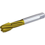
T651 • Metrisch DIN 376 • Form C-Anschnitt • Für Windenergie-Bauteile
Beyond™ HSS-E-PM Gewindebohrer • Sacklochbohrungen
Material Nummer4153885
ISO Katalog NummerT651M300X350R6HX-D6ANSI Katalog NummerT651M300X350R6HX-D6
- P Stahl
Gewindedrehen: Sacklochbohrung
Toleranzklasse: 6HX
DIN 376
Anschnitt Form C (2–3)
HSS-E-PM
Innere Kühlmittelzuführung: Axial: Gewindebohren
Herstellerspezifikationen: M
Spiralwinkel Gewindebohrer: 15°
Sending to {{cadTool}} in progress...
Downloaded file will be available after import in the {{cadTool}} tool library.

| Material Nummer | 4153885 |
| ISO Katalog Nummer | T651M300X350R6HX-D6 |
| ANSI Katalog Nummer | T651M300X350R6HX-D6 |
| Sorte | KP6525 |
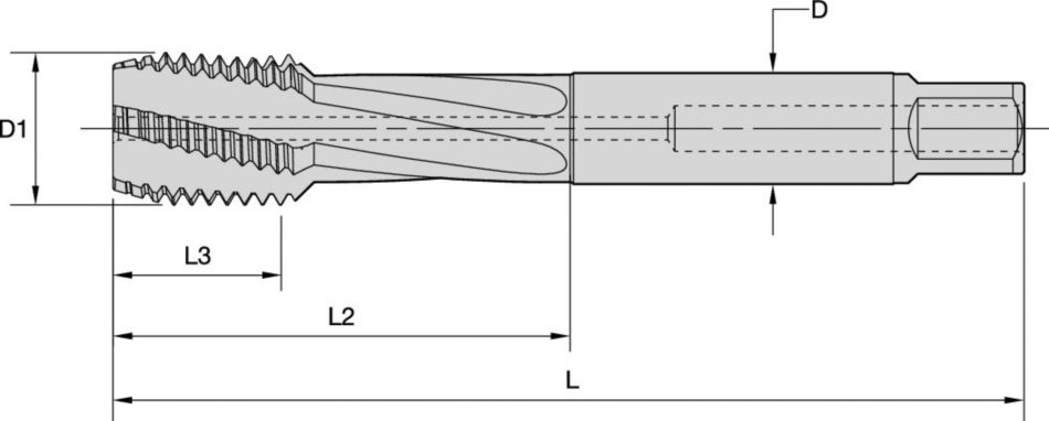
| [D1-TDZ] Gewindedurchmessergröße | M30 X 3,5 |
| [L] Gesamtlänge | 180 mm |
| [L] Gesamtlänge | 7.09 in |
| [L3] Gewindelänge | 35 mm |
| [L3] Gewindelänge | 1.38 in |
| [L2] Nutzbare Länge | 91 mm |
| [L2] Nutzbare Länge | 3.58 in |
| [D] Adapter/Schaft/Bohrungsdurchmesser | 22 mm |
| [D] Adapter/Schaft/Bohrungsdurchmesser | .8661 in |
| [Z] Anzahl der Spannuten | 5 |
| Abmessungsstandard | DIN 376 |
| Gewindetoleranzklasse ISO | 6HX-I |
Werkstoffe
- Stahl
Uses and application
Gewindedrehen: Sacklochbohrung
Toleranzklasse: 6HX
DIN 376
Anschnitt Form C (2–3)
HSS-E-PM
Innere Kühlmittelzuführung: Axial: Gewindebohren
Herstellerspezifikationen: M
Spiralwinkel Gewindebohrer: 15°
Grades

KP6525
Beschichtetes HSS-E-PM. PVD – beschichtet mit einer warm- und verschleißfesten Beschichtung mit hohem Vanadiumgehalt. HSS-Substrat aus Kobaltmetallpulver beschichtet mit einer verschleißfesten TiCN-Basisschicht und einer reibungsarmen TiN-Deckschicht. Anwendung in Stahl, Gusseisen und Aluminiumguss mit Silizium.
Features and benefits
- KP6525 TiCN + TiN für das Gewindebohren in Stahl und Gusseisen.
Lösung erstellen, um Vorschübe und Geschwindigkeiten zu berechnen
Nachdem Sie eine Lösung erstellt haben, wählen Sie einfach das Symbol für Vorschübe und Geschwindigkeiten und unser System gibt Ihnen Empfehlungen. Sie können die Informationen anpassen, indem Sie Ihre Maschine und Spezifikationen hinzufügen oder Anpassungen mithilfe der Schieberegler vornehmen.
Toleranz
Toleranzen
| Schaft Toleranz | |
| D | Toleranz h6 + / - |
| 12 | +0, -0,011 |
| 20 | +0, -0,013 |
| 32 | +0, -0,016 |
DIN 371
| D1 | Steigung | D | L | L3* | L2 | L5 | S10 |
| M3 | 0,5 | 3,5 | 56 | 11 | 18 | 6 | 2,7 |
| M3,5 | 0,6 | 4 | 56 | 12 | 20 | 6 | 3 |
| M4 | 0,7 | 4,5 | 63 | 13 | 21 | 6 | 3,4 |
| M4,5 | 0,75 | 6 | 70 | 16 | 25 | 8 | 4,9 |
| M5 | 0,8 | 6 | 70 | 16 | 25 | 8 | 4,9 |
| M6 | 1 | 6 | 80 | 19 | 30 | 8 | 4,9 |
| M7 | 1 | 7 | 80 | 19 | 30 | 8 | 5,5 |
| M8 | 0,75 | 8 | 80 | 18 | 30 | 9 | 6,2 |
| M8 | 1,25 | 8 | 90 | 22 | 35 | 9 | 6,2 |
| M9 | 0,75 | 9 | 80 | 18 | 30 | 10 | 7 |
| M9 | 1,25 | 9 | 90 | 22 | 35 | 10 | 7 |
| M10 | 1 | 10 | 90 | 20 | 35 | 11 | 8 |
| M10 | 1,5 | 10 | 100 | 24 | 39 | 11 | 8 |
DIN 374
| Steigung | |||||||
| D1 | Minimum | Maximum | D | L | L3* | L5 | S10 |
| M8 | 0,2 | 0,75 | 6 | 80 | 18 | 8 | 4,9 |
| M8 | — | 1 | 6 | 90 | 22 | 8 | 4,9 |
| M9 | 0,2 | 0,75 | 7 | 80 | 18 | 8 | 5,5 |
| M9 | — | 1 | 7 | 90 | 22 | 8 | 5,5 |
| M10 | 0,2 | 1 | 7 | 90 | 20 | 8 | 5,5 |
| M10 | — | 1,25 | 7 | 100 | 24 | 8 | 5,5 |
| M11 | 0,35 | 1 | 8 | 90 | 20 | 9 | 6,2 |
| M12 | 0,35 | 1,5 | 9 | 100 | 22 | 10 | 7 |
| M14 | 0,35 | 1,5 | 11 | 100 | 22 | 12 | 9 |
| M16 | 0,35 | 1,5 | 12 | 100 | 22 | 12 | 9 |
| M16 | — | 2 | 12 | 110 | 32 | 12 | 9 |
| M18 | 0,35 | 1,5 | 14 | 110 | 25 | 14 | 11 |
| M18 | — | 2 | 14 | 125 | 34 | 14 | 11 |
| M20 | 0,35 | 1,5 | 16 | 125 | 25 | 15 | 12 |
| M20 | — | 2 | 16 | 140 | 34 | 15 | 12 |
| M22 | 0,35 | 1,5 | 18 | 125 | 25 | 17 | 14,5 |
| M22 | — | 2 | 18 | 140 | 34 | 17 | 14,5 |
| M24 | 0,35 | 2 | 18 | 140 | 28 | 17 | 14,5 |
| M27 | 0,35 | 2 | 20 | 140 | 28 | 19 | 16 |
| M30 | 0,35 | 2 | 22 | 150 | 28 | 21 | 18 |
| M30 | — | 3 | 22 | 180 | 45 | 21 | 18 |
DIN 376
| D1 | Steigung | D | L | L3* | L5 | S10 |
| M8 | 1,25 | 6 | 90 | 22 | 8 | 4,9 |
| M9 | 1,25 | 7 | 90 | 22 | 8 | 5,5 |
| M10 | 1,5 | 7 | 100 | 24 | 8 | 5,5 |
| M11 | 1,5 | 8 | 100 | 24 | 9 | 6,2 |
| M12 | 1,75 | 9 | 110 | 28 | 10 | 7 |
| M14 | 2 | 11 | 110 | 30 | 12 | 9 |
| M16 | 2 | 12 | 110 | 32 | 12 | 9 |
| M18 | 2,5 | 14 | 125 | 34 | 14 | 11 |
| M20 | 2,5 | 16 | 140 | 34 | 15 | 12 |
| M22 | 2,5 | 18 | 140 | 34 | 17 | 14,5 |
| M24 | 3 | 18 | 160 | 38 | 17 | 14,5 |
| M27 | 3 | 20 | 160 | 38 | 19 | 16 |
| M30 | 3,5 | 22 | 180 | 45 | 21 | 18 |
| M33 | 3,5 | 25 | 180 | 50 | 23 | 20 |
| M36 | 4 | 28 | 200 | 56 | 25 | 22 |
| M39 | 4 | 32 | 200 | 60 | 27 | 24 |
| M42 | 4,5 | 32 | 200 | 60 | 27 | 24 |
| M45 | 4,5 | 36 | 220 | 65 | 32 | 29 |
JIS, Typ 3, metrisch, Normalgewinde
| D1 | Steigung | D | L | L3 | L5 | S10 |
| M8 | 1,25 | 6,2 | 70 | 22 | 8 | 5 |
| M9 | 1,25 | 7 | 72 | 22 | 8 | 5,5 |
| M10 | 1,5 | 7 | 75 | 24 | 8 | 5,5 |
| M11 | 1,5 | 8 | 80 | 25 | 9 | 6 |
| M12 | 1,75 | 8,5 | 82 | 29 | 9 | 6,5 |
| M14 | 2 | 10,5 | 88 | 30 | 11 | 8 |
| M16 | 2 | 12,5 | 95 | 32 | 13 | 10 |
| M18 | 2,5 | 14 | 100 | 37 | 14 | 11 |
| M20 | 2,5 | 15 | 105 | 37 | 15 | 12 |
| M22 | 2,5 | 17 | 115 | 38 | 16 | 13 |
| M24 | 3 | 19 | 120 | 45 | 18 | 15 |
Anwendungsdaten
| HSS-E-PM Taps • Grades KP6505 KP6525 KM6515 | ||||||||||||||||
| Tapping Operation | Ausführung des Gewindebohrers | Grade1 | Schnittgeschwindigkeit | |||||||||||||
| Startwert | ||||||||||||||||
| m/min | 3 | 5 | 10 | 15 | 20 | 25 | 30 | 35 | 40 | 45 | 50 | 55 | 60 | |||
| SFM | 10 | 16 | 33 | 49 | 66 | 82 | 98 | 115 | 131 | 148 | 164 | 180 | 197 | |||
| P1 • Low-Carbon Steels, Long Chipping • Content: C 0.25% • Tensile Strength RM (MPa*): 530 • Hardness (HB) or HRC: 125 | ||||||||||||||||
| Through Holes | T620 | KP6525 | 38 | 30 | 45 | |||||||||||
| 125 | 98 | 148 | ||||||||||||||
| Blind Holes | T630 | KP6525 | 23 | 18 | 27 | |||||||||||
| 75 | 59 | 89 | ||||||||||||||
| P2 • Low-Carbon Steels, Free Machining, and Short Chipping • Content C 0.25% • Tensile Strength RM (MPa*): 650 • Hardness (HB) or HRC: 220 | ||||||||||||||||
| Through Holes | T620 | KP6525 | 33 | 25 | 40 | |||||||||||
| 108 | 82 | 131 | ||||||||||||||
| Blind Holes | T630 | KP6525 | 20 | 15 | 25 | |||||||||||
| 65 | 49 | 82 | ||||||||||||||
| P3 • Medium- and High-Plain Carbon Steels, Low-Alloyed • Content C | ||||||||||||||||
| Through Holes | T620 | KP6525 | 28 | 20 | 35 | |||||||||||
| 92 | 66 | 115 | ||||||||||||||
| Blind Holes | T630 | KP6525 | 17 | 12 | 21 | |||||||||||
| 55 | 59 | 69 | ||||||||||||||
| P5 • Ferritic, Martensitic, and PH Stainless Steels • Content C= 0-0.4% • Tensile Strength RM (MPa*): 600–850 • Hardness (HB) HRC: 330 | ||||||||||||||||
| Through Holes | T620 | KP6525 | 18 | 10 | 25 | |||||||||||
| 59 | 33 | 82 | ||||||||||||||
| Blind Holes | T630 | KP6525 | 11 | 6 | 15 | |||||||||||
| 35 | 20 | 49 | ||||||||||||||
| P6 • High-Strength Ferritic, Martensitic, and PH Stainless Steels • Content C=0.1-0.6% • Tensile Strength RM (MPa*): 900-1350 • Hardness (HB) HRC: 350–450 | ||||||||||||||||
| Through Holes | T620 | KP6525 | 10 | 5 | 15 | |||||||||||
| 33 | 16 | 49 | ||||||||||||||
| Blind Holes | T630 | KP6525 | 6 | 3 | 9 | |||||||||||
| 20 | 10 | 30 | ||||||||||||||
| M1 • Austenitic Stainless Steel • Content C=0.05-0.15% • Tensile Strength RM (MPa*): 650 • Hardness (HB) or HRC: 130-200 | ||||||||||||||||
| Through Holes | T620 | KM6515 | 15 | 10 | 20 | |||||||||||
| 49 | 33 | 66 | ||||||||||||||
| Blind Holes | T630 | KM6515 | 9 | 6 | 12 | |||||||||||
| 30 | 20 | 39 | ||||||||||||||
| M2 • High-Strength Austenitic Stainless and Cast Stainless Steels • Content C=0.05-0.15% • Tensile Strength RM (MPa*): 500 - 700 • Hardness (HB) or HRC: 150-230 | ||||||||||||||||
| Through Holes | T620 | KM6515 | 15 | 10 | 20 | |||||||||||
| 49 | 33 | 66 | ||||||||||||||
| Blind Holes | T630 | KM6515 | 9 | 6 | 12 | |||||||||||
| 30 | 20 | 39 | ||||||||||||||
| M3 • Duplex Steel • Content C=0.05-0.2 % • Tensile Strength RM (MPa*): 900 • Hardness (HB) HRC: 135-275 | ||||||||||||||||
| Through Holes | T620 | KM6515 | 15 | 10 | 20 | |||||||||||
| 49 | 33 | 66 | ||||||||||||||
| Blind Holes | T630 | KM6515 | 9 | 6 | 12 | |||||||||||
| 30 | 20 | 39 | ||||||||||||||
| K1 • Cast and Low-Strength Ductile Irons • Tensile Strength RM (MPa*): 150-400 • Hardness (HB) or HRC: 120-290 | ||||||||||||||||
| Through Holes | T640 | KP6525 | 45 | 30 | 60 | |||||||||||
| 148 | 98 | 197 | ||||||||||||||
| Blind Holes | T640 | KP6525 | 27 | 18 | 36 | |||||||||||
| 90 | 59 | 118 | ||||||||||||||
| K2 • Low- and Medium-Strength CGI and Ductile Irons • Tensile Strength RM (MPa*): 400-600 • Hardness (HB) or HRC: 130-260 | ||||||||||||||||
| Through Holes | T640 | KP6525 | 38 | 25 | 50 | |||||||||||
| 125 | 82 | 164 | ||||||||||||||
| Blind Holes | T640 | KP6525 | 23 | 15 | 30 | |||||||||||
| 75 | 49 | 98 | ||||||||||||||
| K3 • High-Strength Ductile and Austempered Ductile Iron • Tensile Strength RM (MPa*): 600-900 • Hardness (HB) or HRC: 180-350 | ||||||||||||||||
| Through Holes | T640 | KP6525 | 30 | 20 | 40 | |||||||||||
| 98 | 66 | 131 | ||||||||||||||
| Blind Holes | T640 | KP6525 | 18 | 12 | 25 | |||||||||||
| 59 | 39 | 82 | ||||||||||||||
| HSS-E-PM Taps • Grades KP6505 KP6525 KM6515 | ||||||||||||||||
| Tapping Operation | Ausführung des Gewindebohrers | Sorte | Schnittgeschwindigkeit | |||||||||||||
| Startwert | ||||||||||||||||
| m/min | 3 | 5 | 10 | 15 | 20 | 25 | 30 | 35 | 40 | 45 | 50 | 55 | 60 | |||
| SFM | 10 | 16 | 33 | 49 | 66 | 82 | 98 | 115 | 131 | 148 | 164 | 180 | 197 | |||
| P1 • Low-Carbon Steels, Long Chipping • Content: C 0.25% • Tensile Strength RM (MPa*): 530 • Hardness (HB) or HRC: 125 | ||||||||||||||||
| Through Holes | T620 | KP6525 | 38 | 30 | 45 | |||||||||||
| 125 | 98 | 148 | ||||||||||||||
| Blind Holes | T630 | KP6525 | 23 | 18 | 27 | |||||||||||
| 75 | 59 | 89 | ||||||||||||||
| P2 • Low-Carbon Steels, Free Machining, and Short Chipping • Content C 0.25% • Tensile Strength RM (MPa*): 650 • Hardness (HB) or HRC: 220 | ||||||||||||||||
| Through Holes | T620 | KP6525 | 33 | 25 | 40 | |||||||||||
| 108 | 82 | 131 | ||||||||||||||
| Blind Holes | T630 | KP6525 | 20 | 15 | 25 | |||||||||||
| 65 | 49 | 82 | ||||||||||||||
| P3 • Medium- and High-Plain Carbon Steels, Low-Alloyed • Content C | ||||||||||||||||
| Through Holes | T620 | KP6525 | 28 | 20 | 35 | |||||||||||
| 92 | 66 | 115 | ||||||||||||||
| Blind Holes | T630 | KP6525 | 17 | 12 | 21 | |||||||||||
| 55 | 59 | 69 | ||||||||||||||
| P5 • Ferritic, Martensitic, and PH Stainless Steels • Content C= 0-0.4% • Tensile Strength RM (MPa*): 600–850 • Hardness (HB) HRC: 330 | ||||||||||||||||
| Through Holes | T620 | KP6525 | 18 | 10 | 25 | |||||||||||
| 59 | 33 | 82 | ||||||||||||||
| Blind Holes | T630 | KP6525 | 11 | 6 | 15 | |||||||||||
| 35 | 20 | 49 | ||||||||||||||
| P6 • High-Strength Ferritic, Martensitic, and PH Stainless Steels • Content C=0.1-0.6% • Tensile Strength RM (MPa*): 900-1350 • Hardness (HB) HRC: 350–450 | ||||||||||||||||
| Through Holes | T620 | KP6525 | 10 | 5 | 15 | |||||||||||
| 33 | 16 | 49 | ||||||||||||||
| Blind Holes | T630 | KP6525 | 6 | 3 | 9 | |||||||||||
| 20 | 10 | 30 | ||||||||||||||
| M1 • Austenitic Stainless Steel • Content C=0.05-0.15% • Tensile Strength RM (MPa*): 650 • Hardness (HB) or HRC: 130-200 | ||||||||||||||||
| Through Holes | T620 | KM6515 | 15 | 10 | 20 | |||||||||||
| 49 | 33 | 66 | ||||||||||||||
| Blind Holes | T630 | KM6515 | 9 | 6 | 12 | |||||||||||
| 30 | 20 | 39 | ||||||||||||||
| M2 • High-Strength Austenitic Stainless and Cast Stainless Steels • Content C=0.05-0.15% • Tensile Strength RM (MPa*): 500 - 700 • Hardness (HB) or HRC: 150-230 | ||||||||||||||||
| Through Holes | T620 | KM6515 | 15 | 10 | 20 | |||||||||||
| 49 | 33 | 66 | ||||||||||||||
| Blind Holes | T630 | KM6515 | 9 | 6 | 12 | |||||||||||
| 30 | 20 | 39 | ||||||||||||||
| M3 • Duplex Steel • Content C=0.05-0.2 % • Tensile Strength RM (MPa*): 900 • Hardness (HB) HRC: 135-275 | ||||||||||||||||
| Through Holes | T620 | KM6515 | 15 | 10 | 20 | |||||||||||
| 49 | 33 | 66 | ||||||||||||||
| Blind Holes | T630 | KM6515 | 9 | 6 | 12 | |||||||||||
| 30 | 20 | 39 | ||||||||||||||
| K1 • Cast and Low-Strength Ductile Irons • Tensile Strength RM (MPa*): 150-400 • Hardness (HB) or HRC: 120-290 | ||||||||||||||||
| Through Holes | T640 | KP6525 | 45 | 30 | 60 | |||||||||||
| 148 | 98 | 197 | ||||||||||||||
| Blind Holes | T640 | KP6525 | 27 | 18 | 36 | |||||||||||
| 90 | 59 | 118 | ||||||||||||||
| K2 • Low- and Medium-Strength CGI and Ductile Irons • Tensile Strength RM (MPa*): 400-600 • Hardness (HB) or HRC: 130-260 | ||||||||||||||||
| Through Holes | T640 | KP6525 | 38 | 25 | 50 | |||||||||||
| 125 | 82 | 164 | ||||||||||||||
| Blind Holes | T640 | KP6525 | 23 | 15 | 30 | |||||||||||
| 75 | 49 | 98 | ||||||||||||||
| K3 • High-Strength Ductile and Austempered Ductile Iron • Tensile Strength RM (MPa*): 600-900 • Hardness (HB) or HRC: 180-350 | ||||||||||||||||
| Through Holes | T640 | KP6525 | 30 | 20 | 40 | |||||||||||
| 98 | 66 | 131 | ||||||||||||||
| Blind Holes | T640 | KP6525 | 18 | 12 | 25 | |||||||||||
| 59 | 39 | 82 | ||||||||||||||
CAD Drawings Models
Can’t find the file type you’re looking for?
Product data
I have read and accepted the Terms & Conditions of use


