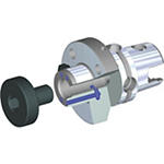
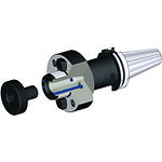
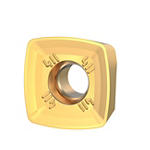
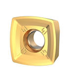
Produit similaire à:
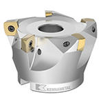
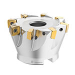
7792VXD12 Series • Shell Mill • Metric
High-Feed copy milling cutter for multiple materials.
Numéro de matériel5659130
Ref. ISO Catalogue7792VXD12-160Z7RRef. ANSI Catalogue7792VXD12-160Z7R
- P Acier
- M Acier inoxydable
- K Fonte
- N Non ferreux
- S Alliages hautes températures
- H Matériaux trempés
Spiral Circular
Slotting: Shoulder
Surfaçage
Fraisage hélicoïdal
Ramping : Ébauche
Usinage de poches
Lamage
Fraisage en plongée : Bout hémisphérique
Inclined Square End Mill
Sending to {{cadTool}} in progress...
Downloaded file will be available after import in the {{cadTool}} tool library.
- Aperçu
- Données d'application
- Téléchargements
- Pièces compatibles côté machine
- Pièces compatibles côté pièce
- Pièces de rechange
- Révision
- FAQ
| Numéro de matériel | 5659130 |
| Ref. ISO Catalogue | 7792VXD12-160Z7R |
| Ref. ANSI Catalogue | 7792VXD12-160Z7R |
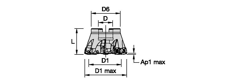
| [D1MAX] Diamètre de coupe maximal | 160 mm |
| [D1MAX] Diamètre de coupe maximal | 6.299 in |
| [D1] Diamètre effectif de coupe | 141.6 mm |
| [D1] Diamètre effectif de coupe | 5.575 in |
| [D] Adaptateur / Queue / Diamètre d’alésage | 40 mm |
| [D] Adaptateur / Queue / Diamètre d’alésage | 1.575 in |
| [D6] Diamètre du moyeu | 110 mm |
| [D6] Diamètre du moyeu | 4.331 in |
| [L] Longueur totale | 63 mm |
| [L] Longueur totale | 2.48 in |
| [AP1MAX] 1re profondeur de coupe maximale | 2.5 mm |
| [AP1MAX] 1re profondeur de coupe maximale | .098 in |
| [Z] Nombre de goujures | 7 |
Matériaux de pièce à usiner
- Acier
- Acier inoxydable
- Fonte
- Non ferreux
- Alliages hautes températures
- Matériaux trempés
Uses and application
Spiral Circular
Slotting: Shoulder
Surfaçage
Fraisage hélicoïdal
Ramping : Ébauche
Usinage de poches
Lamage
Fraisage en plongée : Bout hémisphérique
Inclined Square End Mill
Features and benefits
- Internal coolant supply
- Positive design to support low cutting forces and applications with long overhang
Créez une Solution pour calculer les avances et vitesses
Après avoir créé une Solution, choisissez simplement l'icône "Avances et Vitesses" et notre système vous fournira ses recommandations. Vous pouvez les personnaliser en ajoutant votre machine et vos spécifications techniques, ou en ajustant votre demande à l'aide des curseurs.
Guide de sélection des plaquettes • IC 12
| 7792 Series • IC12 • Insert Selection Guide | ||||||
| Groupe Matières | Travaux légers | Applications générales | Travaux lourds | |||
| – | (géomètrie légère) | – | (géomètrie solide) | |||
| – | résistance à l’usure |  | ténacité | |||
| – | Géométrie | Nuance | Géométrie | Nuance | Géométrie | Nuance |
| P1-P2 | ...M41 | KCPM40 | …M41 | KCPM40 | …GP | KCPM40 |
| P3-P4 | ...M41 | KCPM40 | …D411 | SP6519 | …D41 | KCPM40 |
| P5-P6 | ...M41 | KCPM40 | ...D41 | SP6519 | ...D41 | X500 |
| M1-M2 | ...M41 | KCSM40 | ...D411 | KCSM40 | ...D41 | KCSM40 |
| M3 | ...M41 | KCSM40 | ...D41 | KCSM40 | ...D41 | KCSM40 |
| K1-K2 | …M | KCK20B | …M | KCK20B | …D | KCPK30 |
| K3 | …M | KCK20B | …M | KCK20B | …D | KCPK30 |
| N1-N2 | – | – | – | – | – | – |
| N3 | – | – | – | – | – | – |
| S1-S2 | ...M41 | X500 | ...D411 | KCSM40 | ...D41 | KCSM40 |
| S3 | ...M41 | X500 | ...D411 | KCSM40 | ...D41 | KCSM40 |
| S4 | ...M41 | X500 | ...D411 | KCSM40 | ...D41 | KCSM40 |
| H1 | …M | KCKP10 | …M | KCKP10 | …D | KCPM40 |
Feeds
| 7792 Series • IC12 • Recommended Starting Feeds [IPT] | |||||||
| Géométrie de plaquette | Avance par dent de départ recommandée (Fz) en relation avec le % de l'Engagement Radial (ae) | ||||||
| DOC | 30% | 40–100% | |||||
| (Inch) | L | M | H | L | M | H | |
| .S..D | 0.1 | 0.009 | 0.024 | 0.036 | 0.009 | 0.022 | 0.032 |
| .S..D | 0.7 | 0.011 | 0.028 | 0.042 | 0.010 | 0.026 | 0.038 |
| .S..D | 0.55 | 0.013 | 0.031 | 0.047 | 0.012 | 0.029 | 0.043 |
| .E..D41 | 0.1 | 0.007 | 0.021 | 0.033 | 0.006 | 0.019 | 0.030 |
| .E..D41 | 0.7 | 0.008 | 0.025 | 0.039 | 0.007 | 0.023 | 0.036 |
| .E..D41 | 0.55 | 0.009 | 0.028 | 0.044 | 0.008 | 0.026 | 0.040 |
| .E..D411 | 0.1 | 0.007 | 0.021 | 0.033 | 0.006 | 0.019 | 0.030 |
| .E..D411 | 0.7 | 0.008 | 0.025 | 0.039 | 0.007 | 0.023 | 0.036 |
| .E..D411 | 0.55 | 0.009 | 0.028 | 0.044 | 0.008 | 0.026 | 0.040 |
| .S..GP | 0.1 | 0.009 | 0.024 | 0.035 | 0.009 | 0.022 | 0.032 |
| .S..GP | 0.7 | 0.011 | 0.028 | 0.042 | 0.010 | 0.026 | 0.038 |
| .S..GP | 0.55 | 0.013 | 0.031 | 0.047 | 0.012 | 0.029 | 0.043 |
| .S...M | 0.072 | 0.009 | 0.024 | 0.036 | 0.009 | 0.022 | 0.032 |
| .S...M | 0.55 | 0.013 | 0.031 | 0.047 | 0.012 | 0.029 | 0.043 |
| .E...M41 | 0.072 | 0.007 | 0.021 | 0.033 | 0.006 | 0.019 | 0.030 |
| .E..M41 | 0.55 | 0.009 | 0.028 | 0.044 | 0.008 | 0.026 | 0.040 |
| L = Light Machining; M = Medium Machining; H = Heavy Machining NOTE: Use Light Machining values as starting feed rate. | |||||||
| 7792 Series • IC12 • Recommended Starting Feeds for Plunging [IPT] | ||||
| Géométrie de plaquette |  | Avance par dent (fz) programmée | ||
| L | M | H | ||
| .S..D | 0.004 | 0.009 | 0.014 | |
| .E..D41 | 0.003 | 0.008 | 0.012 | |
| .E..D411 | 0.003 | 0.008 | 0.012 | |
| .S..GP | 0.004 | 0.009 | 0.014 | |
| .S..M | 0.004 | 0.009 | 0.014 | |
| .E..M41 | 0.003 | 0.008 | 0.012 | |
| L = Light Machining; M = Medium Machining; H = Heavy Machining NOTE: Use Light Machining values as starting feed rate. | ||||
| 7792 Series • IC12 • Recommended Starting Feeds [mm/th] | |||||||
| Géométrie de plaquette | Avance par dent de départ recommandée (Fz) en relation avec le % de l'Engagement Radial (ae) | ||||||
| DOC | 30% | 40–100% | |||||
| (mm) | L | M | H | L | M | H | |
| .S..D | 2,5 | 0,24 | 0,61 | 0,89 | 0,22 | 0,55 | 0,82 |
| .S..D | 1,7 | 0,29 | 0,73 | 1,08 | 0,27 | 0,67 | 0,98 |
| .S..D | 1,3 | 0,33 | 0,83 | 1,22 | 0,30 | 0,76 | 1,12 |
| .E..D41 | 2,5 | 0,17 | 0,54 | 0,83 | 0,15 | 0,49 | 0,76 |
| .E..D41 | 1,7 | 0,20 | 0,64 | 1,00 | 0,19 | 0,59 | 0,92 |
| .E..D41 | 1,3 | 0,23 | 0,73 | 1,14 | 0,21 | 0,67 | 1,04 |
| .E..D411 | 2,5 | 0,17 | 0,54 | 0,83 | 0,15 | 0,49 | 0,76 |
| .E..D411 | 1,7 | 0,20 | 0,64 | 1,00 | 0,19 | 0,59 | 0,92 |
| .E..D411 | 1,3 | 0,23 | 0,73 | 1,14 | 0,21 | 0,67 | 1,04 |
| .S..GP | 2,5 | 0,24 | 0,61 | 0,91 | 0,22 | 0,55 | 0,83 |
| .S..GP | 1,7 | 0,29 | 0,73 | 1,10 | 0,27 | 0,67 | 1,00 |
| .S..GP | 1,3 | 0,33 | 0,83 | 1,25 | 0,30 | 0,76 | 1,14 |
| .S...M | 1,84 | 0,24 | 0,61 | 0,89 | 0,22 | 0,55 | 0,82 |
| .S...M | 1,3 | 0,33 | 0,83 | 1,22 | 0,30 | 0,76 | 1,12 |
| .E..M41 | 1,84 | 0,17 | 0,54 | 0,83 | 0,15 | 0,49 | 0,76 |
| .E..M41 | 1,3 | 0,23 | 0,73 | 1,14 | 0,21 | 0,67 | 1,04 |
| L = Light Machining; M = Medium Machining; H = Heavy Machining NOTE: Use Light Machining values as starting feed rate. | |||||||
| 7792 Series • IC12 • Recommended Starting Feeds for Plunging [mm/th] | ||||
| Géométrie de plaquette |  | Avance par dent (fz) programmée | ||
| L | M | H | ||
| .S..D | 0,10 | 0,25 | 0,38 | |
| .E..D41 | 0,07 | 0,23 | 0,35 | |
| .E..D411 | 0,07 | 0,23 | 0,35 | |
| .S..GP | 0,10 | 0,25 | 0,38 | |
| .S..M | 0,10 | 0,25 | 0,38 | |
| .E..M41 | 0,07 | 0,23 | 0,35 | |
| L = Light Machining; M = Medium Machining; H = Heavy Machining NOTE: Use Light Machining values as starting feed rate. | ||||
Speeds
| 7792 Series IC12 • Recommended Starting Speed [SFM] | ||||||||||||||||||||||||||||||||||
| nuance | KC522M | KC725M | KCK15 | KCPK30 | KCKP10 | KCK20B | KCPM40 | KCSM40 | SP6519 | X400 | X500 | |||||||||||||||||||||||
| Chip Thickness hex Inch | Mini | Maxi | Mini | Maxi | Mini | Maxi | Mini | Maxi | Mini | Maxi | Mini | Maxi | Mini | Maxi | Mini | Maxi | Mini | Maxi | Mini | Maxi | Mini | Maxi | ||||||||||||
| Groupe Matières | Maxi | Départ | Mini | Maxi | Départ | Mini | Maxi | Départ | Mini | Maxi | Départ | Mini | Maxi | Départ | Mini | Maxi | Départ | Mini | Maxi | Départ | Mini | Maxi | Départ | Mini | Maxi | Départ | Mini | Maxi | Départ | Mini | Maxi | Départ | Mini | |
| P | 1 | 1085 | 935 | 885 | 855 | 755 | 705 | – | – | – | 1495 | 1295 | 1215 | 985 | 970 | 855 | – | – | – | 970 | 855 | 805 | 1150 | 1050 | 985 | 970 | 705 | 425 | 855 | 625 | 395 | 885 | 655 | 425 |
| 2 | 900 | 785 | 655 | 720 | 625 | 525 | – | – | – | 920 | 835 | 755 | 1015 | 900 | 785 | – | – | – | 820 | 705 | 590 | 985 | 885 | 720 | 855 | 625 | 375 | 755 | 560 | 345 | 785 | 920 | 375 | |
| 3 | 835 | 705 | 575 | 655 | 560 | 460 | – | – | – | 835 | 755 | 675 | 900 | 785 | 675 | – | – | – | 755 | 640 | 525 | 920 | 785 | 640 | 755 | 540 | 330 | 655 | 490 | 310 | 690 | 510 | 330 | |
| 4 | 740 | 605 | 490 | 590 | 490 | 395 | – | – | – | 740 | 605 | 525 | 785 | 675 | 525 | – | – | – | 675 | 560 | 445 | 785 | 675 | 540 | 575 | 410 | 245 | 490 | 360 | 230 | 525 | 395 | 245 | |
| 5 | 605 | 560 | 490 | 490 | 445 | 395 | – | – | – | 625 | 560 | 490 | 675 | 525 | 410 | – | – | – | 560 | 510 | 445 | 655 | 590 | 525 | 460 | 345 | 230 | – | – | – | 425 | 330 | 230 | |
| 6 | 540 | 410 | 330 | 425 | 330 | 260 | – | – | – | 525 | 445 | 360 | 525 | 410 | 360 | – | – | – | 490 | 375 | 295 | 590 | 460 | 330 | 395 | 280 | 165 | – | – | – | 360 | 260 | 165 | |
| M | 1 | 675 | 590 | 540 | 560 | 490 | 445 | – | – | – | 675 | 605 | 510 | – | – | – | – | – | – | 640 | 560 | 510 | 855 | 690 | 605 | 885 | 640 | 375 | – | – | – | 820 | 605 | 375 |
| 2 | 605 | 525 | 425 | 510 | 425 | 360 | – | – | – | 605 | 525 | 460 | – | – | – | – | – | – | 575 | 490 | 410 | 770 | 590 | 475 | 770 | 560 | 345 | – | – | – | 720 | 525 | 330 | |
| 3 | 460 | 395 | 310 | 375 | 330 | 260 | – | – | – | 475 | 425 | 375 | – | – | – | – | – | – | 425 | 375 | 295 | 575 | 475 | 360 | 640 | 460 | 280 | – | – | – | 590 | 425 | 260 | |
| K | 1 | 755 | 675 | 605 | – | – | – | 1380 | 1265 | 1115 | 970 | 870 | 785 | 1345 | 1085 | 785 | 1180 | 950 | 805 | – | – | – | – | – | – | – | – | – | – | – | – | – | – | – |
| 2 | 590 | 525 | 490 | – | – | – | 1100 | 970 | 900 | 770 | 690 | 625 | 920 | 805 | 625 | 920 | 755 | 640 | – | – | – | – | – | – | – | – | – | – | – | – | – | – | – | |
| 3 | 490 | 445 | 395 | – | – | – | 920 | 820 | 755 | 640 | 575 | 525 | 785 | 640 | 525 | 690 | 575 | 460 | – | – | – | – | – | – | – | – | – | – | – | – | – | – | – | |
| N | 1 | – | – | – | – | – | – | – | – | – | – | – | – | – | – | – | – | – | – | – | – | – | – | – | – | – | – | – | – | – | – | – | – | – |
| 2 | – | – | – | – | – | – | – | – | – | – | – | – | – | – | – | – | – | – | – | – | – | – | – | – | – | – | – | – | – | – | – | – | – | |
| 3 | – | – | – | – | – | – | – | – | – | – | – | – | – | – | – | – | – | – | – | – | – | – | – | – | – | – | – | – | – | – | – | – | – | |
| S | 1 | 130 | 115 | 80 | 115 | 100 | 80 | – | – | – | – | – | – | – | – | – | – | – | – | 130 | 115 | 100 | 165 | 130 | 80 | 180 | 130 | 65 | – | – | – | 150 | 115 | 80 |
| 2 | 130 | 115 | 80 | 115 | 100 | 80 | – | – | – | – | – | – | – | – | – | – | – | – | 130 | 115 | 100 | 180 | 130 | 80 | 150 | 115 | 65 | – | – | – | 150 | 100 | 65 | |
| 3 | 165 | 130 | 80 | 150 | 115 | 80 | – | – | – | – | – | – | – | – | – | – | – | – | 165 | 130 | 100 | 215 | 150 | 100 | 180 | 130 | 80 | – | – | – | 165 | 130 | 80 | |
| 4 | 165 | 150 | 115 | 165 | 150 | 100 | – | – | – | 165 | 150 | 115 | – | – | – | – | – | – | 180 | 165 | 115 | 245 | 195 | 130 | 260 | 180 | 115 | – | – | – | 195 | 165 | 115 | |
| H | 1 | 395 | 295 | 230 | – | – | – | – | – | – | – | – | – | 460 | 360 | 295 | – | – | – | – | – | – | – | – | – | – | – | – | 310 | 230 | 150 | – | – | – |
| 2 | – | – | – | – | – | – | – | – | – | – | – | – | – | – | – | – | – | – | – | – | – | – | – | – | – | – | – | 260 | 195 | 115 | – | – | – | |
| Recommended Starting Speed are pointing to 90° Shoulder Milling . Starting Speed for Face and Copy Milling can be Increased by 20 %. As the average chip thickness increases, speed should be decreased. Material groups P, M, K and H show recommended starting speeds for dry machining. For wet machining, reduce speed by 20%. Material groups N and S show recommended starting speeds for wet machining. Not recommended for dry machining. | ||||||||||||||||||||||||||||||||||
Vitesses de départ recommandées [m/mn]
| 7792 Series IC12 • Recommended Starting Speed [m/min] | ||||||||||||||||||||||||||||||||||
| nuance | KC522M | KC725M | KCK15 | KCPK30 | KCKP10 | KCK20B | KCPM40 | KCSM40 | SP6519 | X400 | X500 | |||||||||||||||||||||||
| Epaisseur copeau hm mm | Mini | Maxi | Mini | Maxi | Mini | Maxi | Mini | Maxi | Mini | Maxi | Mini | Maxi | Mini | Maxi | Mini | Maxi | Mini | Maxi | Mini | Maxi | Mini | Maxi | ||||||||||||
| Groupe Matières | Maxi | Départ | Mini | Maxi | Départ | Mini | Maxi | Départ | Mini | Maxi | Départ | Mini | Maxi | Départ | Mini | Maxi | Départ | Mini | Maxi | Départ | Mini | Maxi | Départ | Mini | Maxi | Départ | Mini | Maxi | Départ | Mini | Maxi | Départ | Mini | |
| P | 1 | 330 | 285 | 270 | 260 | 230 | 215 | – | – | – | 455 | 395 | 370 | 300 | 295 | 260 | – | – | – | 295 | 260 | 245 | 350 | 320 | 300 | 295 | 215 | 130 | 260 | 190 | 120 | 270 | 200 | 130 |
| 2 | 275 | 240 | 200 | 220 | 190 | 160 | – | – | – | 280 | 255 | 230 | 310 | 275 | 240 | – | – | – | 250 | 215 | 180 | 300 | 270 | 220 | 260 | 190 | 115 | 230 | 170 | 105 | 240 | 280 | 115 | |
| 3 | 255 | 215 | 175 | 200 | 170 | 140 | – | – | – | 255 | 230 | 205 | 275 | 240 | 205 | – | – | – | 230 | 195 | 160 | 280 | 240 | 195 | 230 | 165 | 100 | 200 | 150 | 95 | 210 | 155 | 100 | |
| 4 | 225 | 185 | 150 | 180 | 150 | 120 | – | – | – | 225 | 185 | 160 | 240 | 205 | 160 | – | – | – | 205 | 170 | 135 | 240 | 205 | 165 | 175 | 125 | 75 | 150 | 110 | 70 | 160 | 120 | 75 | |
| 5 | 185 | 170 | 150 | 150 | 135 | 120 | – | – | – | 190 | 170 | 150 | 205 | 160 | 125 | – | – | – | 170 | 155 | 135 | 200 | 180 | 160 | 140 | 105 | 70 | – | – | – | 130 | 100 | 70 | |
| 6 | 165 | 125 | 100 | 130 | 100 | 80 | – | – | – | 160 | 135 | 110 | 160 | 125 | 110 | – | – | – | 150 | 115 | 90 | 180 | 140 | 100 | 120 | 85 | 50 | – | – | – | 110 | 80 | 50 | |
| M | 1 | 205 | 180 | 165 | 170 | 150 | 135 | – | – | – | 205 | 185 | 155 | – | – | – | – | – | – | 195 | 170 | 155 | 260 | 210 | 185 | 270 | 195 | 115 | – | – | – | 250 | 185 | 115 |
| 2 | 185 | 160 | 130 | 155 | 130 | 110 | – | – | – | 185 | 160 | 140 | – | – | – | – | – | – | 175 | 150 | 125 | 235 | 180 | 145 | 235 | 170 | 105 | – | – | – | 220 | 160 | 100 | |
| 3 | 140 | 120 | 95 | 115 | 100 | 80 | – | – | – | 145 | 130 | 115 | – | – | – | – | – | – | 130 | 115 | 90 | 175 | 145 | 110 | 195 | 140 | 85 | – | – | – | 180 | 130 | 80 | |
| K | 1 | 230 | 205 | 185 | – | – | – | 420 | 385 | 340 | 295 | 265 | 240 | 410 | 330 | 240 | 360 | 290 | 245 | – | – | – | – | – | – | – | – | – | – | – | – | – | – | – |
| 2 | 180 | 160 | 150 | – | – | – | 335 | 295 | 275 | 235 | 210 | 190 | 280 | 245 | 190 | 280 | 230 | 195 | – | – | – | – | – | – | – | – | – | – | – | – | – | – | – | |
| 3 | 150 | 135 | 120 | – | – | – | 280 | 250 | 230 | 195 | 175 | 160 | 240 | 195 | 160 | 210 | 175 | 140 | – | – | – | – | – | – | – | – | – | – | – | – | – | – | – | |
| N | 1 | – | – | – | – | – | – | – | – | – | – | – | – | – | – | – | – | – | – | – | – | – | – | – | – | – | – | – | – | – | – | – | – | – |
| 2 | – | – | – | – | – | – | – | – | – | – | – | – | – | – | – | – | – | – | – | – | – | – | – | – | – | – | – | – | – | – | – | – | – | |
| 3 | – | – | – | – | – | – | – | – | – | – | – | – | – | – | – | – | – | – | – | – | – | – | – | – | – | – | – | – | – | – | – | – | – | |
| S | 1 | 40 | 35 | 25 | 35 | 30 | 25 | – | – | – | – | – | – | – | – | – | – | – | – | 40 | 35 | 30 | 50 | 40 | 25 | 55 | 40 | 20 | – | – | – | 45 | 35 | 25 |
| 2 | 40 | 35 | 25 | 35 | 30 | 25 | – | – | – | – | – | – | – | – | – | – | – | – | 40 | 35 | 30 | 55 | 40 | 25 | 45 | 35 | 20 | – | – | – | 45 | 30 | 20 | |
| 3 | 50 | 40 | 25 | 45 | 35 | 25 | – | – | – | – | – | – | – | – | – | – | – | – | 50 | 40 | 30 | 65 | 45 | 30 | 55 | 40 | 25 | – | – | – | 50 | 40 | 25 | |
| 4 | 50 | 45 | 35 | 50 | 45 | 30 | – | – | – | 50 | 45 | 35 | – | – | – | – | – | – | 55 | 50 | 35 | 75 | 60 | 40 | 80 | 55 | 35 | – | – | – | 60 | 50 | 35 | |
| H | 1 | 120 | 90 | 70 | – | – | – | – | – | – | – | – | – | 140 | 110 | 90 | – | – | – | – | – | – | – | – | – | – | – | – | 95 | 70 | 45 | – | – | – |
| 2 | – | – | – | – | – | – | – | – | – | – | – | – | – | – | – | – | – | – | – | – | – | – | – | – | – | – | – | 80 | 60 | 35 | – | – | – | |
| Recommended Starting Speed are pointing to 90° Shoulder Milling . Starting Speed for Face and Copy Milling can be Increased by 20 %. As the average chip thickness increases, speed should be decreased. Material groups P, M, K and H show recommended starting speeds for dry machining. For wet machining, reduce speed by 20%. Material groups N and S show recommended starting speeds for wet machining. Not recommended for dry machining. | ||||||||||||||||||||||||||||||||||
Données d'application
| 7792 Series IC12 • Ramping Application Data • Curved Edges • Inch | |||||
| D1 maxi | Angle de coupe (°) | ae maxi | Pas de surfaçage | DH min [Inch] - (min hole diameter) | DH min (diamètre d'alésage mini) |
| 1.25 | 1.85° | 0.362 | 0.526 | 1.133 | 1.921 |
| 1.50 | 0.95° | 0.362 | 0.770 | 2.133 | 2.921 |
| 2.00 | 0.9° | 0.362 | 1.276 | 3.133 | 3.921 |
| 2.50 | 0.6° | 0.362 | 1.776 | 4.133 | 4.921 |
| 3.00 | 0.45° | 0.362 | 2.276 | 5.133 | 5.921 |
| 4.00 | 0.31° | 0.362 | 3.270 | 7.133 | 7.921 |
| 5.00 | 0.24° | 0.362 | 4.270 | 9.133 | 9.921 |
| 6.00 | 0.19° | 0.362 | 5.270 | 11.133 | 11.921 |
| NOTE: Maximum ramp angle decreases as nose radius increases. | |||||
| 7792 Series IC12 • Ramping Application Data • Straight-Edged Inserts • Inch | |||||
| D1 maxi | Angle de coupe (°) | ae maxi | Pas de surfaçage | DH min [Inch] - (min hole diameter) | DH min (diamètre d'alésage mini) |
| 1.25 | 3.56° | 0.362 | 0.604 | 1.133 | 1.921 |
| 1.50 | 2.22° | 0.362 | 0.854 | 2.133 | 2.921 |
| 2.00 | 1.25° | 0.362 | 1.354 | 3.133 | 3.921 |
| 2.50 | 0.86° | 0.362 | 1.854 | 4.133 | 4.921 |
| 3.00 | 0.66° | 0.362 | 2.354 | 5.133 | 5.921 |
| 4.00 | 0.45° | 0.362 | 3.354 | 7.133 | 7.921 |
| 5.00 | 0.34° | 0.362 | 4.354 | 9.133 | 9.921 |
| 6.00 | 0.275° | 0.362 | 5.354 | 11.133 | 11.921 |
| NOTE: Maximum ramp angle decreases as nose radius increases. | |||||
| 7792 Series IC12 • Programing Data • Curved Edges • Inch [inch] | |||
| IC | Rayon de Pointe | R | L |
| 06 | 0.031 | 0.057 | 0.016 |
| 09 | 0.031 | 0.079 | 0.028 |
| 0.047 | 0.089 | 0.026 | |
| 12 | 0.031 | 0.098 | 0.040 |
| 0.047 | 0.107 | 0.038 | |
| 16 | 0.047 | 0.164 | 0.057 |
| 7792 Series IC12 • Programing Data • Straight-Edged Inserts • Inch [inch] | |||
| IC | Rayon de Pointe | R | L |
| 06 | 0.031 | 0.057 | 0.021 |
| 09 | 0.031 | 0.084 | 0.040 |
| 0.047 | 0.088 | 0.037 | |
| 12 | 0.031 | 0.097 | 0.052 |
| 0.047 | 0.109 | 0.050 | |
| 0.079 | 0.134 | 0.044 | |
| 16 | 0.047 | 0.140 | 0.072 |
| CNC Program • Corner Radius Definition The use of common CAD/CAM systems requires a round insert dimension to be known for cavity machining. For finish pass applications: Wiper facet for finishing use max. feed 0.031". | |||
| 7792 Series IC12 • Ramping Application Data • Curved Edges • Metric | |||||
| D1 maxi | Angle de coupe (°) | ae maxi | Pas de surfaçage | DH min [mm] - (min hole diameter) | DH min (diamètre d'alésage mini) |
| 32 | 1.8° | 9,2 | 10,6 | 42 | 62 |
| 35 | 1.8° | 9,2 | 16,6 | 48 | 68 |
| 40 | 1.4° | 9,2 | 21,6 | 58 | 78 |
| 42 | 1.3° | 9,2 | 23,6 | 62 | 82 |
| 50 | 0.9° | 9,2 | 31,6 | 78 | 98 |
| 52 | 0.8° | 9,2 | 33,6 | 82 | 102 |
| 63 | 0.6° | 9,2 | 44,6 | 104 | 124 |
| 66 | 0.5° | 9,2 | 47,6 | 110 | 130 |
| 80 | 0.5° | 9,2 | 61,6 | 138 | 158 |
| 100 | 0.3° | 9,2 | 81,6 | 178 | 198 |
| 125 | 0.2° | 9,2 | 106,6 | 228 | 248 |
| 160 | 0.2° | 9,2 | 141,6 | 298 | 318 |
| NOTE: Maximum ramp angle decreases as nose radius increases. | |||||
| 7792 Series IC12 • Ramping Application Data • Straight-Edged Inserts • Metric | |||||
| D1 maxi | Angle de coupe (°) | ae maxi | Pas de surfaçage | DH min [mm] - (min hole diameter) | DH min (diamètre d'alésage mini) |
| 32 | 3.1° | 9,2 | 15,6 | 42 | 62 |
| 35 | 2.45° | 9,2 | 18,6 | 48 | 68 |
| 40 | 1.8° | 9,2 | 23,6 | 58 | 78 |
| 42 | 1.6° | 9,2 | 25,6 | 62 | 82 |
| 50 | 1.1° | 9,2 | 33,6 | 78 | 98 |
| 52 | 1.1° | 9,2 | 35,6 | 82 | 102 |
| 63 | 0.8° | 9,2 | 46,6 | 104 | 124 |
| 66 | 0.75° | 9,2 | 49,6 | 110 | 130 |
| 80 | 0.55° | 9,2 | 63,6 | 138 | 158 |
| 100 | 0.4° | 9,2 | 83,6 | 178 | 198 |
| 125 | 0.3° | 9,2 | 108,6 | 228 | 248 |
| 160 | 0.25° | 9,2 | 143,6 | 298 | 318 |
| NOTE: Maximum ramp angle decreases as nose radius increases. | |||||
| 7792 Series IC12 • Programing Data • Curved Edges • Metric [mm] | |||
| IC | Rayon de Pointe | R | L |
| 06 | 0,8 | 1,37 | 0,4 |
| 09 | 0,8 | 2,01 | 0,73 |
| 1,2 | 2,27 | 0,67 | |
| 12 | 0,8 | 2,5 | 1,02 |
| 1,2 | 2,73 | 0,97 | |
| 16 | 1,2 | 4,18 | 1,46 |
| 7792 Series IC12 • Programing Data • Straight-Edged Inserts • Metric [mm] | |||
| IC | Rayon de Pointe | R | L |
| 06 | 0,8 | 1,46 | 0,529 |
| 09 | 0,8 | 2,13 | 1,025 |
| 1,2 | 2,25 | 0,95 | |
| 12 | 0,8 | 2,46 | 1,33 |
| 1,2 | 2,79 | 1,27 | |
| 2 | 3,42 | 1,13 | |
| 16 | 1,2 | 3,56 | 1,82 |
| CNC Program • Corner Radius Definition The use of common CAD/CAM systems requires a round insert dimension to be known for cavity machining. For finish pass applications: Wiper facet for finishing use max. feed 0,8mm. | |||
CAD Drawings Models
Can’t find the file type you’re looking for?
Product data
I have read and accepted the Terms & Conditions of use
