Producto similar a:
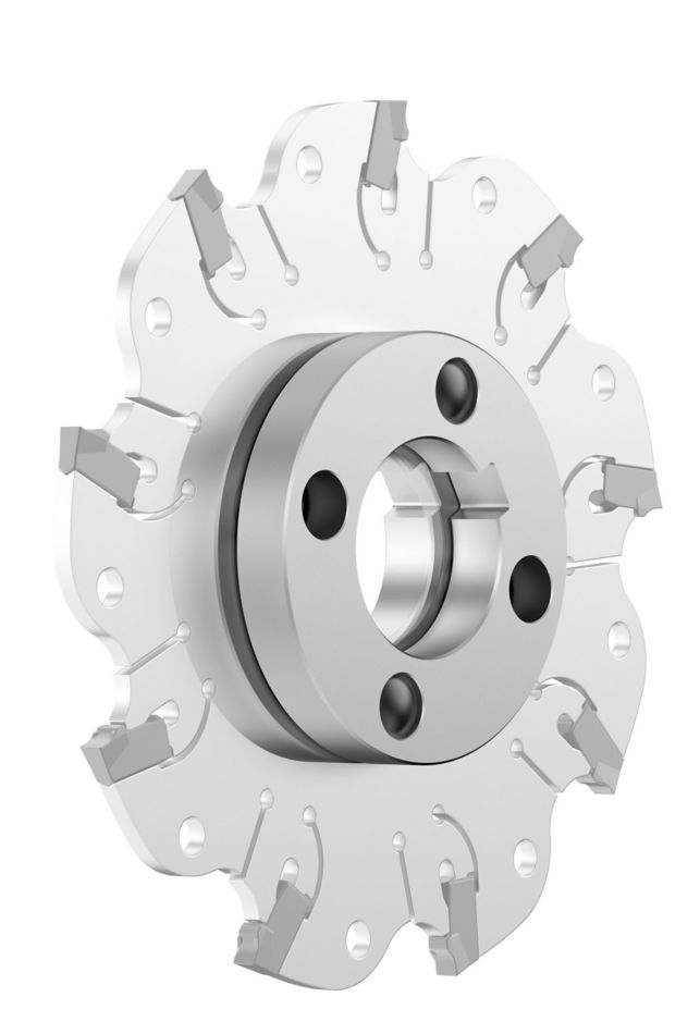
KVNS™ A2™ • Arbor Mount • Metric
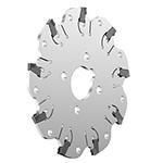
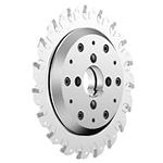
Slot milling cutter for multiple materials
Número de material1246142
Referencia ISO4.97123130Referencia ANSI4.97123130
- P Acero
- M Acero inoxidable
- K Fundición
- N Materiales no ferrosos
- S Aleaciones de alta temperatura
Ranurado: Lateral con dimensiones AE/AP
Sending to {{cadTool}} in progress...
Downloaded file will be available after import in the {{cadTool}} tool library.
- Información general
- Datos de aplicación
- Descargas
- Piezas compatibles Lado máquina
- Piezas compatibles Lado de la pieza
- Piezas de recambio
- Comentarios
- Preguntas y Respuestas
| Número de material | 1246142 |
| Referencia ISO | 4.97123130 |
| Referencia ANSI | 4.97123130 |
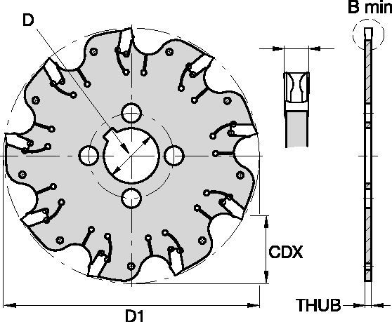
| Ancho de corte Mínimo [BM] | 3 mm |
| Ancho de corte Mínimo [BM] | .1181 in |
| Diámetro de corte efectivo [D1] | 125 mm |
| Diámetro de corte efectivo [D1] | 4.921 in |
| Profundidad de corte máxima radial [CDX] | 35 mm |
| Profundidad de corte máxima radial [CDX] | 1.378 in |
| Adaptador/Mango/Diá int [D] | 32 mm |
| Adaptador/Mango/Diá int [D] | 1.259 in |
| Grosor de núcleo [THUB] | 2.4 mm |
| Grosor de núcleo [THUB] | .0945 in |
| Número de plaquitas | 11 |
| Peso en kilogramos | 0.17 |
| Calibre de plaquita | 3.90030____ |
| RPM máx. | 2600 |
Materiales de la pieza de trabajo
- Acero
- Acero inoxidable
- Fundición
- Materiales no ferrosos
- Aleaciones de alta temperatura
Uses and application
Ranurado: Lateral con dimensiones AE/AP
Features and benefits
- Self-clamping insert seat with fixed stop.
- Excellent for all flat-bottom slotting and cut-off operations.
- Two drive rings required for each cutter body. They must be ordered separately, and in pairs of two.
- For cutter diameters 200mm and 250mm support rings are optional (instead of drive rings). Support rings also must be ordered separately, and in pairs of two.
Crear una solución para calcular la velocidad y el avance
Después de crear una solución, sólo tiene que elegir el icono Avance y Velocidad y nuestro sistema le ofrecerá recomendaciones. Puede personalizar la información añadiendo su máquina y especificaciones o realizar ajustes utilizando los controles deslizantes.
Insert Selection
Guía para la selección de plaquitas
| KVNS™ A2™ Slotting Cutters • Insert Selection Guide | ||||||
| Grupo de materiales | Mecanizado ligero | Aplicaciones generales | Mecanizado intensivo | |||
| – | (Geometría ligera) | (Geometría fuerte) | ||||
| – | resistencia |  | tenacidad | |||
| – | Geometría | Calidad | Geometría | Calidad | Geometría | Calidad |
| P1-P2 | .S..GD | KCPK30 | .S..GD | KCPK30 | .S..GB | KCPK30 |
| P3-P4 | .S..GD | KCPK30 | .S..GD | KCPK30 | .S..GB | KCPK30 |
| P5-P6 | .S..GD | KCPK30 | .S..GB | KCPK30 | .S..GB | KCPK30 |
| M1-M2 | .S..GD | KCPK30 | .S..GD | KCPK30 | .S..GB | KCPK30 |
| M3 | .S..GD | KCPK30 | .S..GB | KCPK30 | .S..GB | KCPK30 |
| K1-K2 | .S..GD | KCPK30 | .S..GD | KCPK30 | .S..GB | KCPK30 |
| K3 | .S..GD | KCPK30 | .S..GD | KCPK30 | .S..GB | KCPK30 |
| N1-N2 | – | – | – | – | – | – |
| N3 | – | – | – | – | – | – |
| S1-S2 | – | – | – | – | – | – |
| S3 | – | – | – | – | – | – |
| S4 | – | – | – | – | – | – |
| H1 | – | – | – | – | – | – |
Feeds
Avances iniciales recomendados [mm]
| KVNS™ A2™ Series • Recommended Starting Feeds [mm/th] | |||||||||||||||
| Geometría de plaquita | Avance inicial recomendado por diente (Fz) en relación con % de contacto radial (ae) | ||||||||||||||
| 5% | 10% | 20% | 30% | 40–100% | |||||||||||
| L | M | H | L | M | H | L | M | H | L | M | H | L | M | H | |
| .S..GD | 0,23 | 0,46 | 0,71 | 0,17 | 0,33 | 0,51 | 0,13 | 0,25 | 0,38 | 0,11 | 0,22 | 0,33 | 0,10 | 0,20 | 0,30 |
| .S..GB | 0,23 | 0,46 | 0,74 | 0,17 | 0,33 | 0,54 | 0,13 | 0,25 | 0,40 | 0,11 | 0,22 | 0,35 | 0,10 | 0,20 | 0,32 |
| L = Light Machining; M = Medium Machining; H = Heavy Machining NOTE: Use "Light Machining" values as starting feed rate. | |||||||||||||||
Recommended Starting Feeds [IPT]
| KVNS™ A2™ Series • Recommended Starting Feeds [IPT] | |||||||||||||||
| Geometría de plaquita | Avance inicial recomendado por diente (Fz) en relación con % de contacto radial (ae) | ||||||||||||||
| 5% | 10% | 20% | 30% | 40–100% | |||||||||||
| L | M | H | L | M | H | L | M | H | L | M | H | L | M | H | |
| .S..GD | 0.009 | 0.017 | 0.026 | 0.007 | 0.013 | 0.019 | 0.005 | 0.009 | 0.014 | 0.004 | 0.008 | 0.012 | 0.004 | 0.008 | 0.011 |
| .S..GB | 0.009 | 0.017 | 0.028 | 0.007 | 0.013 | 0.020 | 0.005 | 0.009 | 0.015 | 0.004 | 0.008 | 0.013 | 0.004 | 0.008 | 0.012 |
| L = Light Machining; M = Medium Machining; H = Heavy Machining NOTE: Use "Light Machining" values as starting feed rate. | |||||||||||||||
Speeds
Velocidades iniciales recomendadas (m/min)
| KVNS™ A2™ Series • Recommended Starting Speed [m/min] | |||||||
| Calidad | KCPK30 | KMF | |||||
| Grosor de viruta hex mm | Mín | Máx. | Mín | Máx. | |||
| Grupo de materiales | Máx. | Inicio | Mín | Máx. | Inicio | Mín | |
| P | 1 | 455 | 395 | 370 | – | – | – |
| 2 | 280 | 255 | 230 | – | – | – | |
| 3 | 255 | 230 | 205 | – | – | – | |
| 4 | 225 | 185 | 160 | – | – | – | |
| 5 | 190 | 170 | 150 | – | – | – | |
| 6 | 160 | 135 | 110 | – | – | – | |
| M | 1 | 205 | 185 | 155 | – | – | – |
| 2 | 185 | 160 | 140 | – | – | – | |
| 3 | 145 | 130 | 115 | – | – | – | |
| K | 1 | 295 | 265 | 240 | – | – | – |
| 2 | 235 | 210 | 190 | – | – | – | |
| 3 | 195 | 175 | 160 | – | – | – | |
| N | 1 | – | – | – | 335 | 298 | 271 |
| 2 | – | – | – | 335 | 298 | 271 | |
| 3 | – | – | – | 219 | 198 | 170 | |
| S | 1 | – | – | – | 30 | 24 | 20 |
| 2 | – | – | – | 30 | 24 | 20 | |
| 3 | – | – | – | 30 | 24 | 20 | |
| 4 | 50 | 45 | 35 | 24 | 24 | 24 | |
| H | 1 | – | – | – | – | – | – |
| Recommended Starting Speed are pointing to 90° Shoulder Milling . Starting Speed for Face and Copy Milling can be Increased by 20 %. As the average chip thickness increases, speed should be decreased. Material groups P, M, K and H show recommended starting speeds for dry machining. For wet machining, reduce speed by 20%. Material groups N and S show recommended starting speeds for wet machining. Not recommended for dry machining. | |||||||
Recommended Starting Speeds [SFM]
| KVNS™ A2™ Series • Recommended Starting Speed [SFM] | |||||||
| Calidad | KCPK30 | KMF | |||||
| Chip Thickness hex Inch | Mín | Máx. | Mín | Máx. | |||
| Grupo de materiales | Máx. | Inicio | Mín | Máx. | Inicio | Mín | |
| P | 1 | 1495 | 1295 | 1215 | – | – | – |
| 2 | 920 | 835 | 755 | – | – | – | |
| 3 | 835 | 755 | 675 | – | – | – | |
| 4 | 740 | 605 | 525 | – | – | – | |
| 5 | 625 | 560 | 490 | – | – | – | |
| 6 | 525 | 445 | 360 | – | – | – | |
| M | 1 | 675 | 605 | 510 | – | – | – |
| 2 | 605 | 525 | 460 | – | – | – | |
| 3 | 475 | 425 | 375 | – | – | – | |
| K | 1 | 970 | 870 | 785 | – | – | – |
| 2 | 770 | 690 | 625 | – | – | – | |
| 3 | 640 | 575 | 525 | – | – | – | |
| N | 1 | – | – | – | 1100 | 980 | 890 |
| 2 | – | – | – | 1100 | 980 | 890 | |
| 3 | – | – | – | 720 | 650 | 560 | |
| S | 1 | – | – | – | 100 | 80 | 65 |
| 2 | – | – | – | 100 | 80 | 65 | |
| 3 | – | – | – | 100 | 80 | 65 | |
| 4 | 165 | 150 | 115 | 80 | 80 | 80 | |
| H | 1 | – | – | – | – | – | – |
| Recommended Starting Speed are pointing to 90° Shoulder Milling . Starting Speed for Face and Copy Milling can be Increased by 20 %. As the average chip thickness increases, speed should be decreased. Material groups P, M, K and H show recommended starting speeds for dry machining. For wet machining, reduce speed by 20%. Material groups N and S show recommended starting speeds for wet machining. Not recommended for dry machining. | |||||||
CAD Drawings Models
Can’t find the file type you’re looking for?
Product data
I have read and accepted the Terms & Conditions of use
