Produkt ähnlich wie:
5720 Series • End Mill • Screw-On • Inch
Shoulder milling cutter for high-speed aluminum machining.
Material Nummer5672719
ISO Katalog NummerA5720VZ16SA1.25Z2R2ANSI Katalog NummerA5720VZ16SA1.25Z02R2
- K Gusseisen
- N NE-Metalle
Spiral Circular
Planfräsen
Spiralförmiges Interpolieren
Schräg-Eintauchfräsen Ins Volle
Schaft – Aufschraubbar
Fräsen – Innere Kühlmittelzuführung
Auskammern
Senken
Inclined Square End Mill
Sending to {{cadTool}} in progress...
Downloaded file will be available after import in the {{cadTool}} tool library.
- Überblick
- Anwendungsdaten
- Herunterladen
- Kompatible Teile Maschinenseite
- Kompatible Teile Werkstückseite
- Ersatzteile
- Bewertung
- F&A
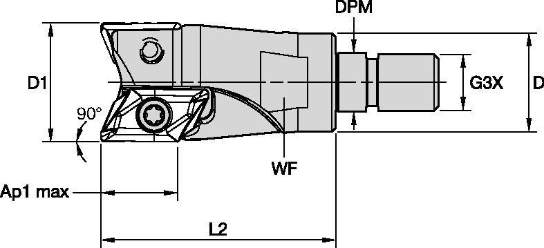
| Material Nummer | 5672719 |
| ISO Katalog Nummer | A5720VZ16SA1.25Z2R2 |
| ANSI Katalog Nummer | A5720VZ16SA1.25Z02R2 |
| [D1] Effektiver Schneidendurchmesser | 31.75 mm |
| [D1] Effektiver Schneidendurchmesser | 1.25 in |
| [D] Adapter/Schaft/Bohrungsdurchmesser | 29 mm |
| [D] Adapter/Schaft/Bohrungsdurchmesser | 1.1417 in |
| [DPM] Führungsdurchmesser Maschinenseite | 17 mm |
| [DPM] Führungsdurchmesser Maschinenseite | 0.6693 in |
| [G3X] Verbindungsgewinde Größe extern | M16 |
| [L2] Kopflänge | 50 mm |
| [L2] Kopflänge | 1.9685 in |
| [WF] Flächenbreite | 24 mm |
| [WF] Flächenbreite | 0.9449 in |
| [AP1MAX] 1. maximale Schnitttiefe | 16 mm |
| [AP1MAX] 1. maximale Schnitttiefe | 0.6299 in |
| Anzahl der Schneidkörper | 2 |
| [Z] Anzahl der Spannuten | 2 |
| Maximaler Eintauchwinkel | 11.5 |
| Gewicht Pfund | 0.45 |
| Max. Drehzahl | 41500 |
Werkstoffe
- Gusseisen
- NE-Metalle
Uses and application
Spiral Circular
Planfräsen
Spiralförmiges Interpolieren
Schräg-Eintauchfräsen Ins Volle
Schaft – Aufschraubbar
Fräsen – Innere Kühlmittelzuführung
Auskammern
Senken
Inclined Square End Mill
Features and benefits
- For pocketing and profiling in aluminum and aluminum alloys.
- Maximum stability in high-speed applications.
- Excellent choice for components with thin walls due to low cutting pressure.
- Internal coolant supply.
- Reinforced pockets for high feed applications and ramping, increasing tool and productivity.
Lösung erstellen, um Vorschübe und Geschwindigkeiten zu berechnen
Nachdem Sie eine Lösung erstellt haben, wählen Sie einfach das Symbol für Vorschübe und Geschwindigkeiten und unser System gibt Ihnen Empfehlungen. Sie können die Informationen anpassen, indem Sie Ihre Maschine und Spezifikationen hinzufügen oder Anpassungen mithilfe der Schieberegler vornehmen.
Feeds
Empfohlene Startwerte für Vorschübe [mm]
| 5720 Series • Recommended Starting Feeds [mm/th] | |||||||||||||||
| Schneidkörper- Geometrie | Empfohlener Start-Vorschub pro Zahn (fz) im Verhältnis zur radialen Schnitttiefe (ae) in % | ||||||||||||||
| 5% | 10% | 20% | 30% | 40–100% | |||||||||||
| L | M | H | L | M | H | L | M | H | L | M | H | L | M | H | |
| ...FR721 | 0,12 | 0.45 | 0.81 | 0,08 | 0.33 | 0.58 | 0,06 | 0.25 | 0.43 | 0,06 | 0.21 | 0.38 | 0,05 | 0.2 | 0.35 |
| ...ER721 | 0.15 | 0.50 | 0.92 | 0.11 | 0.36 | 0.66 | 0.08 | 0.27 | 0.5 | 0.07 | 0,24 | 0.43 | 0.07 | 0,22 | 0,40 |
| L = Light Machining; M = Medium Machining; H = Heavy Machining NOTE: Use "Light Machining" values as starting feed rate. | |||||||||||||||
| 5720 Series • Recommended Starting Feeds [IPT] | |||||||||||||||
| Schneidkörper- Geometrie | Empfohlener Start-Vorschub pro Zahn (fz) im Verhältnis zur radialen Schnitttiefe (ae) in % | ||||||||||||||
| 5% | 10% | 20% | 30% | 40–100% | |||||||||||
| L | M | H | L | M | H | L | M | H | L | M | H | L | M | H | |
| ...FR721 | 0,12 | 0.45 | 0.81 | 0,08 | 0.33 | 0.58 | 0,06 | 0.25 | 0.43 | 0,06 | 0.21 | 0.38 | 0,05 | 0.2 | 0.35 |
| ...ER721 | 0.15 | 0.50 | 0.92 | 0.11 | 0.36 | 0.66 | 0.08 | 0.27 | 0.5 | 0.07 | 0,24 | 0.43 | 0.07 | 0,22 | 0,40 |
| L = Light Machining; M = Medium Machining; H = Heavy Machining NOTE: Use "Light Machining" values as starting feed rate. | |||||||||||||||
Speeds
Empfohlene Startwerte für Schnittgeschwindigkeit [m/min]
| 5720 Series • Recommended Starting Speed [m/min] | ||||
| Schneidstoffsorte | GH1 | |||
| Spandicke hex mm | Min. | Max. | ||
| Werkstoffgruppe | Max. | Startwert | Min. | |
| P | 1 | – | – | – |
| 2 | – | – | – | |
| 3 | – | – | – | |
| 4 | – | – | – | |
| 5 | – | – | – | |
| 6 | – | – | – | |
| M | 1 | – | – | – |
| 2 | – | – | – | |
| 3 | – | – | – | |
| K | 1 | 215 | 140 | 120 |
| 2 | 195 | 120 | 100 | |
| 3 | 180 | 105 | 80 | |
| N | 1 | 795 | 695 | 600 |
| 2 | 615 | 520 | 425 | |
| 3 | 615 | 520 | 425 | |
| S | 1 | – | – | – |
| 2 | – | – | – | |
| 3 | – | – | – | |
| 4 | – | – | – | |
| H | 1 | – | – | – |
| As the average chip thickness increases, speed should be decreased. Material groups P, M, K and H show recommended starting speeds for dry machining. For wet machining, reduce speed by 20%. Material groups N and S show recommended starting speeds for wet machining. Not recommended for dry machining. | ||||
| 5720 Series • Recommended Starting Speed [SFM] | ||||
| Schneidstoffsorte | GH1 | |||
| Chip Thickness hex Inch | Min. | Max. | ||
| Werkstoffgruppe | Max. | Startwert | Min. | |
| P | 1 | – | – | – |
| 2 | – | – | – | |
| 3 | – | – | – | |
| 4 | – | – | – | |
| 5 | – | – | – | |
| 6 | – | – | – | |
| M | 1 | – | – | – |
| 2 | – | – | – | |
| 3 | – | – | – | |
| K | 1 | 705 | 460 | 395 |
| 2 | 640 | 395 | 330 | |
| 3 | 590 | 345 | 260 | |
| N | 1 | 2610 | 2280 | 1970 |
| 2 | 2020 | 1705 | 1395 | |
| 3 | 2020 | 1705 | 1395 | |
| S | 1 | – | – | – |
| 2 | – | – | – | |
| 3 | – | – | – | |
| 4 | – | – | – | |
| H | 1 | – | – | – |
| As the average chip thickness increases, speed should be decreased. Material groups P, M, K and H show recommended starting speeds for dry machining. For wet machining, reduce speed by 20%. Material groups N and S show recommended starting speeds for wet machining. Not recommended for dry machining. | ||||
Insert Selection
Auswahlhilfe für Wendeschneidplatten
| 5720 Series • Insert Selection Guide | ||||||
| Werkstoffgruppe | Leichte Bearbeitung | Allgemeine Anwendung | Schruppbearbeitung | |||
| – | (Leicht schneidende Geometrie) | – | (Stabile Geometrie) | |||
| – | Verschleiß- festigkeit |  | Zähigkeit | |||
| – | Geometrie | Sorte | Geometrie | Sorte | Geometrie | Sorte |
| P1–P2 | – | – | – | – | – | – |
| P3–P4 | – | – | – | – | – | – |
| P5–P6 | – | – | – | – | – | – |
| M1–M2 | – | – | – | – | – | – |
| M3 | – | – | – | – | – | – |
| K1–K2 | – | – | – | – | – | – |
| K3 | – | – | – | – | – | – |
| N1–N2 | .F..721 | GH1 | .F..721 | GH1 | .F..721 | GH1 |
| N3 | .F..721 | GH1 | .F..721 | GH1 | .F..721 | GH1 |
| S1–S2 | – | – | – | – | – | – |
| S3 | – | – | – | – | – | – |
| S4 | – | – | – | – | – | – |
| H1 | – | – | – | – | – | – |
I have read and accepted the Terms & Conditions of use
CAD Drawings Models
Can’t find the file type you’re looking for?
Product data
