Produkt ähnlich wie:
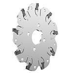
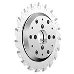
KVNS™ A2™ • Arbor Mount • Inch
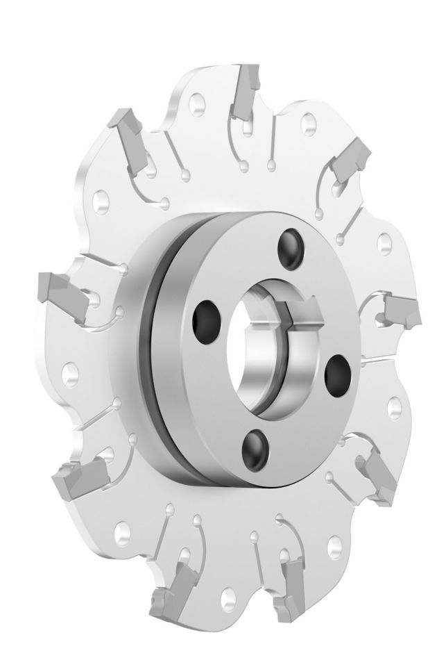
Slot milling cutter for multiple materials
Material Nummer1247721
ISO Katalog NummerKVNS03197ODANSI Katalog NummerKVNS03197OD
Nutenfräsen: Schulter mit AE-/AP-Abmessungen
Sending to {{cadTool}} in progress...
Downloaded file will be available after import in the {{cadTool}} tool library.
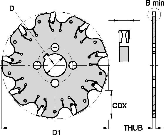
| Material Nummer | 1247721 |
| ISO Katalog Nummer | KVNS03197OD |
| ANSI Katalog Nummer | KVNS03197OD |
| [BM] Schnittbreite Min. | 5 mm |
| [BM] Schnittbreite Min. | .197 in |
| [D1] Effektiver Schneidendurchmesser | 76.2 mm |
| [D1] Effektiver Schneidendurchmesser | 3 in |
| [CDX] Radiale maximale Schnitttiefe | 22.225 mm |
| [CDX] Radiale maximale Schnitttiefe | .875 in |
| [D] Adapter/Schaft/Bohrungsdurchmesser | 15.875 mm |
| [D] Adapter/Schaft/Bohrungsdurchmesser | .625 in |
| [THUB] Nabendicke | 4.4 mm |
| [THUB] Nabendicke | .1732 in |
| Anzahl der Schneidkörper | 5 |
| Gewicht Kilogramm | 0.11 |
| Wendeschneidplatten-Größe | OD_5197__ |
| Max. Drehzahl | 4000 |
Uses and application
Nutenfräsen: Schulter mit AE-/AP-Abmessungen
Features and benefits
- Self-clamping insert seat with fixed stop.
- Excellent for all flat-bottom slotting and cut-off operations.
- Two drive rings required for each cutter body. They must be ordered separately, and in pairs of two.
- For cutter diameters 8" and 10" support rings are optional (instead of drive rings). Support rings also must be ordered separately, and in pairs of two.
Lösung erstellen, um Vorschübe und Geschwindigkeiten zu berechnen
Nachdem Sie eine Lösung erstellt haben, wählen Sie einfach das Symbol für Vorschübe und Geschwindigkeiten und unser System gibt Ihnen Empfehlungen. Sie können die Informationen anpassen, indem Sie Ihre Maschine und Spezifikationen hinzufügen oder Anpassungen mithilfe der Schieberegler vornehmen.
Feeds
Empfohlene Startwerte für Vorschübe [mm]
| KVNS™ A2™ Series • Recommended Starting Feeds [mm/th] | |||||||||||||||
| Schneidkörper- Geometrie | Empfohlener Start-Vorschub pro Zahn (fz) im Verhältnis zur radialen Schnitttiefe (ae) in % | ||||||||||||||
| 5% | 10% | 20% | 30% | 40–100% | |||||||||||
| L | M | H | L | M | H | L | M | H | L | M | H | L | M | H | |
| .S..GD | 0,23 | 0,46 | 0,71 | 0,17 | 0,33 | 0,51 | 0,13 | 0,25 | 0,38 | 0,11 | 0,22 | 0,33 | 0,10 | 0,20 | 0,30 |
| .S..GB | 0,23 | 0,46 | 0,74 | 0,17 | 0,33 | 0,54 | 0,13 | 0,25 | 0,40 | 0,11 | 0,22 | 0,35 | 0,10 | 0,20 | 0,32 |
| L = Light Machining; M = Medium Machining; H = Heavy Machining NOTE: Use "Light Machining" values as starting feed rate. | |||||||||||||||
Recommended Starting Feeds [IPT]
| KVNS™ A2™ Series • Recommended Starting Feeds [IPT] | |||||||||||||||
| Schneidkörper- Geometrie | Empfohlener Start-Vorschub pro Zahn (fz) im Verhältnis zur radialen Schnitttiefe (ae) in % | ||||||||||||||
| 5% | 10% | 20% | 30% | 40–100% | |||||||||||
| L | M | H | L | M | H | L | M | H | L | M | H | L | M | H | |
| .S..GD | 0.009 | 0.017 | 0.026 | 0.007 | 0.013 | 0.019 | 0.005 | 0.009 | 0.014 | 0.004 | 0.008 | 0.012 | 0.004 | 0.008 | 0.011 |
| .S..GB | 0.009 | 0.017 | 0.028 | 0.007 | 0.013 | 0.020 | 0.005 | 0.009 | 0.015 | 0.004 | 0.008 | 0.013 | 0.004 | 0.008 | 0.012 |
| L = Light Machining; M = Medium Machining; H = Heavy Machining NOTE: Use "Light Machining" values as starting feed rate. | |||||||||||||||
Speeds
Empfohlene Startwerte für Schnittgeschwindigkeit [m/min]
| KVNS™ A2™ Series • Recommended Starting Speed [m/min] | |||||||
| Schneidstoffsorte | KCPK30 | KMF | |||||
| Spandicke hex mm | Min. | Max. | Min. | Max. | |||
| Werkstoffgruppe | Max. | Startwert | Min. | Max. | Startwert | Min. | |
| P | 1 | 455 | 395 | 370 | – | – | – |
| 2 | 280 | 255 | 230 | – | – | – | |
| 3 | 255 | 230 | 205 | – | – | – | |
| 4 | 225 | 185 | 160 | – | – | – | |
| 5 | 190 | 170 | 150 | – | – | – | |
| 6 | 160 | 135 | 110 | – | – | – | |
| M | 1 | 205 | 185 | 155 | – | – | – |
| 2 | 185 | 160 | 140 | – | – | – | |
| 3 | 145 | 130 | 115 | – | – | – | |
| K | 1 | 295 | 265 | 240 | – | – | – |
| 2 | 235 | 210 | 190 | – | – | – | |
| 3 | 195 | 175 | 160 | – | – | – | |
| N | 1 | – | – | – | 335 | 298 | 271 |
| 2 | – | – | – | 335 | 298 | 271 | |
| 3 | – | – | – | 219 | 198 | 170 | |
| S | 1 | – | – | – | 30 | 24 | 20 |
| 2 | – | – | – | 30 | 24 | 20 | |
| 3 | – | – | – | 30 | 24 | 20 | |
| 4 | 50 | 45 | 35 | 24 | 24 | 24 | |
| H | 1 | – | – | – | – | – | – |
| Recommended Starting Speed are pointing to 90° Shoulder Milling . Starting Speed for Face and Copy Milling can be Increased by 20 %. As the average chip thickness increases, speed should be decreased. Material groups P, M, K and H show recommended starting speeds for dry machining. For wet machining, reduce speed by 20%. Material groups N and S show recommended starting speeds for wet machining. Not recommended for dry machining. | |||||||
Recommended Starting Speeds [SFM]
| KVNS™ A2™ Series • Recommended Starting Speed [SFM] | |||||||
| Schneidstoffsorte | KCPK30 | KMF | |||||
| Chip Thickness hex Inch | Min. | Max. | Min. | Max. | |||
| Werkstoffgruppe | Max. | Startwert | Min. | Max. | Startwert | Min. | |
| P | 1 | 1495 | 1295 | 1215 | – | – | – |
| 2 | 920 | 835 | 755 | – | – | – | |
| 3 | 835 | 755 | 675 | – | – | – | |
| 4 | 740 | 605 | 525 | – | – | – | |
| 5 | 625 | 560 | 490 | – | – | – | |
| 6 | 525 | 445 | 360 | – | – | – | |
| M | 1 | 675 | 605 | 510 | – | – | – |
| 2 | 605 | 525 | 460 | – | – | – | |
| 3 | 475 | 425 | 375 | – | – | – | |
| K | 1 | 970 | 870 | 785 | – | – | – |
| 2 | 770 | 690 | 625 | – | – | – | |
| 3 | 640 | 575 | 525 | – | – | – | |
| N | 1 | – | – | – | 1100 | 980 | 890 |
| 2 | – | – | – | 1100 | 980 | 890 | |
| 3 | – | – | – | 720 | 650 | 560 | |
| S | 1 | – | – | – | 100 | 80 | 65 |
| 2 | – | – | – | 100 | 80 | 65 | |
| 3 | – | – | – | 100 | 80 | 65 | |
| 4 | 165 | 150 | 115 | 80 | 80 | 80 | |
| H | 1 | – | – | – | – | – | – |
| Recommended Starting Speed are pointing to 90° Shoulder Milling . Starting Speed for Face and Copy Milling can be Increased by 20 %. As the average chip thickness increases, speed should be decreased. Material groups P, M, K and H show recommended starting speeds for dry machining. For wet machining, reduce speed by 20%. Material groups N and S show recommended starting speeds for wet machining. Not recommended for dry machining. | |||||||
Insert Selection
Auswahlhilfe für Schneidkörper
| KVNS™ A2™ Slotting Cutters • Insert Selection Guide | ||||||
| Werkstoffgruppe | Leichte Bearbeitung | Allgemeine Anwendung | Schruppbearbeitung | |||
| – | (Leicht schneidende Geometrie) | (Stabile Geometrie) | ||||
| – | Verschleiß- festigkeit |  | Zähigkeit | |||
| – | Geometrie | Sorte | Geometrie | Sorte | Geometrie | Sorte |
| P1-P2 | .S..GD | KCPK30 | .S..GD | KCPK30 | .S..GB | KCPK30 |
| P3-P4 | .S..GD | KCPK30 | .S..GD | KCPK30 | .S..GB | KCPK30 |
| P5-P6 | .S..GD | KCPK30 | .S..GB | KCPK30 | .S..GB | KCPK30 |
| M1-M2 | .S..GD | KCPK30 | .S..GD | KCPK30 | .S..GB | KCPK30 |
| M3 | .S..GD | KCPK30 | .S..GB | KCPK30 | .S..GB | KCPK30 |
| K1-K2 | .S..GD | KCPK30 | .S..GD | KCPK30 | .S..GB | KCPK30 |
| K3 | .S..GD | KCPK30 | .S..GD | KCPK30 | .S..GB | KCPK30 |
| N1-N2 | – | – | – | – | – | – |
| N3 | – | – | – | – | – | – |
| S1-S2 | – | – | – | – | – | – |
| S3 | – | – | – | – | – | – |
| S4 | – | – | – | – | – | – |
| H1 | – | – | – | – | – | – |
CAD Drawings Models
Can’t find the file type you’re looking for?
Product data
I have read and accepted the Terms & Conditions of use
