Produto semelhante ao:
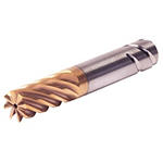
HARVI™ IV • Square End • 8 Flutes • Internal Coolant • Safe-LockTM Shank • Inch
HARVI™ IV Eight Flute End Mill for Roughing and Finishing
Covering the Broadest Range of Applications and Materials
Número de material106359484
Características e benefícios
- Single tool for roughing and finishing to reduce tool setups.
- Proprietary core and flute design with optimum flute spacing for perfect chip formation and highest tool rigidity.
- Developed for highest productivity in titanium, high-temperature alloys, and stainless steels.
- With Safe-Lock for pull-out protection.
Trochoidal Milling
100665610
107038547
Fresamento helicoidal
Fresamento de rampa: blank
Fresamento lateral/fresamento de canto: topo reto
Fresamento de cavidade
| Angle of engagement (phi°) relative to cutting width (Ae) |  | |||||||||
| ae | 2% | 5% | 7.50% | 10% | 15% | 20% | 30% | 40% | 50% | 100% |
| phi - angle of engagement | 16.26 | 25.84 | 31.79 | 36.87 | 45.57 | 53.13 | 66.42 | 78.46 | 90 | 180 |
| Adjustment factors for speed (Vc) and feed (Fz) • METRIC | |||||||
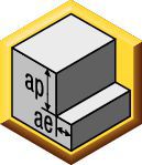
| Maximum cutting width (Ae) for given cutting depth (Ap) | |||||||
| Ap | ≤.125 x D1 | >.125xD1 ≤ .5xD1 | >.5xD1 ≤ 1xD1 | >1xD1 ≤ 2xD1 | >2xD1 ≤ 3xD1 | >3xD1 ≤ 4xD1 | >4 x D1 |
| Max Ae | 100% x D1 | 50% x D1 x KAp | 40% x D1 x KAp | 30% x D1 x KAp | 20% x D1 x KAp | 15% x D1 x KAp | 10% x D1 x KAp |
| Note: KAp value is given on the Speed and Feed table, according to the type of workpiece material selected. | |||||||
| Adjustment factors for speed (Vc) and feed (Fz) • METRIC | ||||||||||
| Ae/D1 | ≤2% | >2% ≤ 5% | >5 ≤ 7.5% | >7.5% ≤ 10% | >10% ≤ 15% | >15% ≤ 20% | >20% ≤ 30% | >30% ≤ 40% | >40% ≤ 50% | >50% ≤ 100% |
| Kv | 3 | 2.5 | 1.9 | 1.4 | 1.35 | 1.3 | 1.2 | 1.1 | 1 | 0.9 |
| KFz | 3.28 | 2.3 | 1.95 | 1.7 | 1.5 | 1.25 | 1.09 | 1.02 | 1 | 1 |
| Note: Identify the radial engagement per percentage of the tool diameter (Ae/D1). That column will give you the factor to multiply the Base SMF and Base IPT on the Speed and Feed original table Kv = Factor to multiply the Speed by KFz = Factor to multiply the Feed by | ||||||||||
| To calculate application specific cutting data, please use KAp, Kv, and Kfz from tables above for adaption of cutting speeds and feeds respectively: Maximum Ae=(Ap1Max/D1) * KAp * D1 Vc new = Vc * Kv IPT new = IPT * KFz | Sample Calculation Material: S4 D1: 25 mm Ap: 2xD1 Max Ae: 30% x KAp x D1 --- 30% * 0.7 * D1 = 21%xD1 SFM: Base x Kv --- 45 * 1.2 = 54 IPT: Base x KFz --- 0.081 * 1.09 = 0.088 | Final cutting data recommendation: Max Ae = 0.3 * 0.7 * 25 = 5.25 mm Vc new = 45 * 1.2 = 54 m/min IPT new = 0.081 * 1.09 = 0.088 mm/th | ||||||||
| Table for Feed and Speed Calculation with Adjustment Factor • METRIC | ||||||||
 | Fresamento lateral (A) | KCSM15A | Avanço Recomendado por faca (fz = mm/f) para fresamento lateral com ae = 10% de D1 | |||||
| Grupo de material | Max Ae Factor (KAp) | Velocidade de corte | 10 | 12 | 16 | 20 | 25 | |
| P | 3 | 1 | 130 | 0.049 | 0.055 | 0.067 | 0.080 | 0.095 |
| 4 | 1 | 100 | 0.044 | 0.049 | 0.059 | 0.069 | 0.081 | |
| 5 | 0.8 | 65 | 0.038 | 0.043 | 0.053 | 0.063 | 0.076 | |
| 6 | 0.7 | 50 | 0.032 | 0.036 | 0.043 | 0.050 | 0.060 | |
| M | 1 | 1 | 80 | 0.049 | 0.055 | 0.067 | 0.080 | 0.095 |
| 2 | 0.8 | 60 | 0.038 | 0.043 | 0.053 | 0.063 | 0.076 | |
| 3 | 0.8 | 60 | 0.032 | 0.036 | 0.043 | 0.050 | 0.060 | |
| S | 1 | 0.5 | 50 | 0.049 | 0.055 | 0.067 | 0.080 | 0.095 |
| 2 | 0.5 | 30 | 0.038 | 0.043 | 0.053 | 0.063 | 0.076 | |
| 3 | 0.5 | 25 | 0.026 | 0.030 | 0.036 | 0.043 | 0.051 | |
| 4 | 0.7 | 45 | 0.041 | 0.051 | 0.061 | 0.069 | 0.081 | |
| H | 1 | 0.8 | 80 | 0.044 | 0.049 | 0.059 | 0.069 | 0.081 |
| 2 | 0.5 | 70 | 0.037 | 0.041 | 0.050 | 0.059 | 0.070 | |
| These guidelines may require variations to achieve optimum results. Above parameters are based on ideal conditions. For smaller taper machining centers, please adjust parameters accordingly on | ||||||||
| Adjustment factors for speed (Vc) and feed (Fz) • INCH | ||||||||||
| Ae/D1 | ≤2% | >2% ≤ 5% | >5 ≤ 7.5% | >7.5% ≤ 10% | >10% ≤ 15% | >15% ≤ 20% | >20% ≤ 30% | >30% ≤ 40% | >40% ≤ 50% | >50% ≤ 100% |
| Kv | 3 | 2.5 | 1.9 | 1.4 | 1.35 | 1.3 | 1.2 | 1.1 | 1 | 0.9 |
| KFz | 3.28 | 2.3 | 1.95 | 1.7 | 1.5 | 1.25 | 1.09 | 1.02 | 1 | 1 |
| Note: Identify the radial engagement per percentage of the tool diameter (Ae/D1). That column will give you the factor to multiply the Base SMF and Base IPT on the Speed and Feed original table Kv = Factor to multiply the Speed by KFz = Factor to multiply the Feed by | ||||||||||
| To calculate application specific cutting data, please use KAp, Kv, and Kfz from tables above for adaption of cutting speeds and feeds respectively: Maximum Ae=(Ap1Max/D1) * KAp * D1 Vc new = Vc * Kv IPT new = IPT * KFz | Sample Calculation Material: S4 D1: 25 mm Ap: 2xD1 Max Ae: 30% x KAp x D1 --- 30% * 0.7 * D1 = 21%xD1 SFM: Base x Kv --- 45 * 1.2 = 54 IPT: Base x KFz --- 0.081 * 1.09 = 0.088 | Final cutting data recommendation: Max Ae = 0.3 * 0.7 * 25 = 5.25 mm Vc new = 45 * 1.2 = 54 m/min IPT new = 0.081 * 1.09 = 0.088 mm/th | ||||||||
| Table for Feed and Speed Calculation with Adjustment Factor • INCH | |||||||||
 | Fresamento lateral (A) | KCSM15A | Recommended feed per tooth (fz=IPT) for side milling | ||||||
| frac. | 3/8 | 1/2 | 5/8 | 3/4 | 1 | ||||
| Grupo de material | Max Ae Factor (KAp) | Velocidade de corte | dec. | 0.375 | 0.500 | 0.625 | 0.750 | 1 | |
| P | 3 | 1 | 420 | IPT | 0.0018 | 0.0023 | 0.0027 | 0.003 | 0.0037 |
| 4 | 1 | 320 | IPT | 0.0016 | 0.0021 | 0.0024 | 0.0026 | 0.0031 | |
| 5 | 0.8 | 210 | IPT | 0.0014 | 0.0018 | 0.0022 | 0.0024 | 0.0029 | |
| 6 | 0.7 | 160 | IPT | 0.0012 | 0.0015 | 0.0018 | 0.0019 | 0.0022 | |
| M | 1 | 1 | 275 | IPT | 0.0018 | 0.0023 | 0.0027 | 0.003 | 0.0037 |
| 2 | 0.8 | 200 | IPT | 0.0014 | 0.0018 | 0.0022 | 0.0024 | 0.0029 | |
| 3 | 0.8 | 200 | IPT | 0.0012 | 0.0015 | 0.0018 | 0.0019 | 0.0022 | |
| S | 1 | 0.5 | 160 | IPT | 0.0018 | 0.0023 | 0.0027 | 0.003 | 0.0037 |
| 2 | 0.5 | 100 | IPT | 0.0014 | 0.0018 | 0.0022 | 0.0024 | 0.0029 | |
| 3 | 0.5 | 80 | IPT | 0.001 | 0.0013 | 0.0014 | 0.0016 | 0.002 | |
| 4 | 0.7 | 160 | IPT | 0.0016 | 0.002 | 0.0024 | 0.0027 | 0.0032 | |
| H | 1 | 0.8 | 260 | IPT | 0.0016 | 0.0021 | 0.0024 | 0.0026 | 0.0031 |
| 2 | 0.5 | 230 | IPT | 0.0014 | 0.0018 | 0.002 | 0.0022 | 0.0026 | |
| These guidelines may require variations to achieve optimum results. Above parameters are based on ideal conditions. For smaller taper machining centers, please adjust parameters accordingly on | |||||||||
| Adjustment factors for speed (Vc) and feed (Fz) • INCH | |||||||
| Maximum cutting width (Ae) for given cutting depth (Ap) | |||||||
| Ap | ≤.125 x D1 | >.125xD1 ≤ .5xD1 | >.5xD1 ≤ 1xD1 | >1xD1 ≤ 2xD1 | >2xD1 ≤ 3xD1 | >3xD1 ≤ 4xD1 | >4 x D1 |
| Max Ae | 100% x D1 | 50% x D1 x KAp | 40% x D1 x KAp | 30% x D1 x KAp | 20% x D1 x KAp | 15% x D1 x KAp | 10% x D1 x KAp |
| Note: KAp value is given on the Speed and Feed table, according to the type of workpiece material selected. | |||||||


