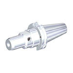
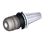
Produto semelhante ao:
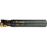
KDMR • Cylindrical Shank • Multifunctional • Inch
Multifunctional Cutter
Número de material3578444
ID do catálogo ISOKDMR1250S125MT16ID do catálogo ANSIKDMR1250S125MT16
- P Steel
- M Stainless Steel
Furação
Fresamento helicoidal
Fresamento de mergulho
Fresamento de rampa: blank
Abertura de canal: ponta esférica
Haste — Cilíndrica lisa
Fresamento — Refrigeração interna
Fresamento de cavidade
Sending to {{cadTool}} in progress...
Downloaded file will be available after import in the {{cadTool}} tool library.
- Visão geral
- Dados de aplicação
- Transferências
- Lado da máquina de peças compatíveis
- Lado da peça de peças compatíveis
- Peças de substituição
- Revisão
- Q&A
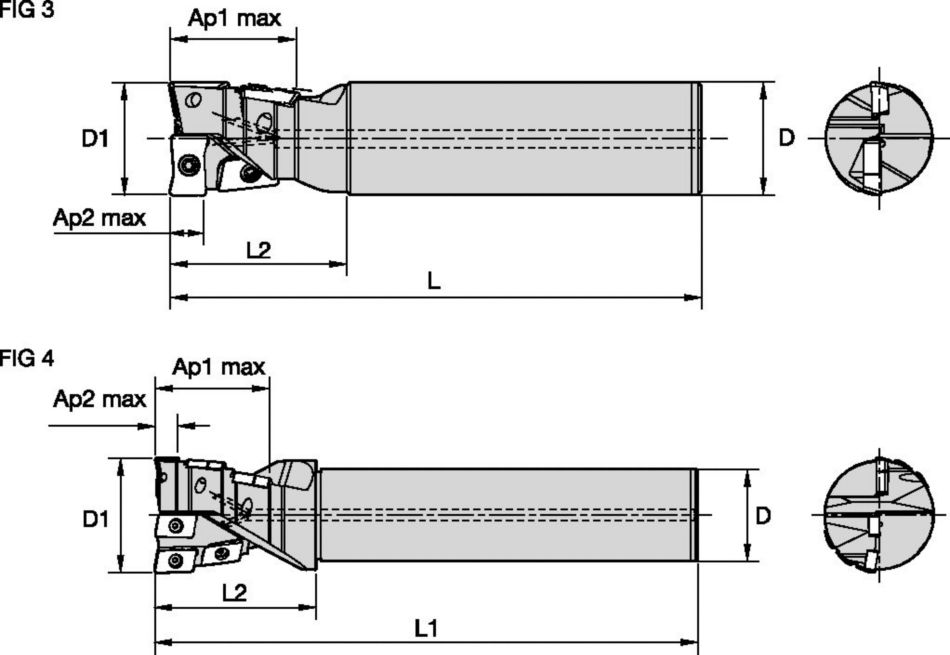
| Número de material | 3578444 |
| ID do catálogo ISO | KDMR1250S125MT16 |
| ID do catálogo ANSI | KDMR1250S125MT16 |
| [D1] Effective Cutting Diameter | 31.75 mm |
| [D1] Effective Cutting Diameter | 1.25 in |
| [D] Adapter / Shank / Bore Diameter | 31.75 mm |
| [D] Adapter / Shank / Bore Diameter | 1.25 in |
| [L] Overall Length | 148.793 mm |
| [L] Overall Length | 5.858 in |
| [L2] Head Length | 48.793 mm |
| [L2] Head Length | 1.921 in |
| [AP1MAX] 1st Maximum Cutting Depth | 35.99 mm |
| [AP1MAX] 1st Maximum Cutting Depth | 1.417 in |
| [AP2MAX] 2nd Maximum Cutting Depth | 9.5 mm |
| [AP2MAX] 2nd Maximum Cutting Depth | 0.374 in |
| Number of Inserts | 4 |
| [Z] Number of Flutes | 2 |
| KYC_CTLG_REF_ILLUS_NUM | FIG 3 |
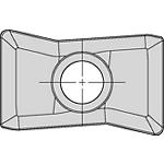
| Gage Insert | GOMT160408ERLD |
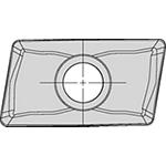
| Gage Insert | JOMT160408ERLF |
| Weight Pounds | 1.8 |
Materiais das peças
- Steel
- Stainless Steel
Usos e aplicações
Furação
Fresamento helicoidal
Fresamento de mergulho
Fresamento de rampa: blank
Abertura de canal: ponta esférica
Haste — Cilíndrica lisa
Fresamento — Refrigeração interna
Fresamento de cavidade
Características e benefícios
- Low cutting forces.
- Reduced shank diameters for access down long side walls.
- Excellent chip evacuation, even machining on an angle.
- When drilling use (1) as the effective number of teeth (Zu).
- Milling to the maximum axial depth of (Ap2), we have (2) effective teeth.
Criar solução para calcular avanços e velocidade
Após criar uma solução basta escolher o ícone Avanços & Velocidades e o nosso sistema irá fornecer recomendações. Pode personalizar as informações adicionando a sua máquina e especificações ou fazer ajustes utilizando os controlos deslizantes.
Avanços
Avanços recomendados iniciais [mm]
| Geometria do Inserto | Avanço por faca inicial recomendado (fz = mm/faca) em relação à % de engajamento radial (ae) | Geometria do Inserto | ||||||||||||||
| 10% | 20% | 30% | 40% | 50–100% | ||||||||||||
| .LD/.LF | 0,14 | 0,34 | 0,51 | 0,11 | 0,25 | 0,38 | 0,09 | 0,22 | 0,33 | 0,09 | 0,21 | 0,31 | 0,08 | 0,20 | 0,30 | .LD/.LF |
| Usinagem leve | Usinagem geral | Usinagem pesada |
Recommended Starting Feeds [IPT]
| Geometria do Inserto | Avanço por faca inicial recomendado (fz = mm/faca) em relação à % de engajamento radial (ae) | Geometria do Inserto | ||||||||||||||
| 10% | 20% | 30% | 40% | 50–100% | ||||||||||||
| .LD/.LF | .006 | .014 | .020 | .004 | .010 | .015 | .004 | .009 | .013 | .003 | .008 | .012 | .003 | .008 | .012 | .LD/.LF |
| Usinagem leve | Usinagem geral | Usinagem pesada |
Velocidades
Velocidades recomendadas iniciais [m/min]
| Grupo de material | KC505M | KC720M | |||||
| P | 1 | – | – | – | 260 | 240 | 215 |
| 2 | – | – | – | 240 | 215 | 190 | |
| 3 | – | – | – | 215 | 190 | 170 | |
| 4 | 360 | 260 | 215 | 190 | 180 | 170 | |
| 5 | 360 | 260 | 215 | 170 | 145 | 120 | |
| 6 | 350 | 240 | 190 | 120 | 95 | 95 | |
| M | 1 | – | – | – | 240 | 215 | 190 |
| 2 | – | – | – | 190 | 170 | 145 | |
| 3 | – | – | – | 145 | 120 | 95 | |
| K | 1 | 190 | 170 | 150 | – | – | – |
| 2 | 175 | 155 | 135 | – | – | – | |
| 3 | 115 | 95 | 75 | – | – | – | |
| N | 1–2 | – | – | – | – | – | – |
| 3 | – | – | – | – | – | – | |
| S | 1 | – | – | – | – | – | – |
| 2 | – | – | – | – | – | – | |
| 3 | – | – | – | – | – | – | |
| 4 | – | – | – | – | – | – | |
| H | 1 | – | – | – | – | – | – |
Recommended Starting Speeds [SFM]
| Grupo de material | KC505M | KC720M | |||||
| P | 1 | – | – | – | 860 | 790 | 710 |
| 2 | – | – | – | 790 | 710 | 630 | |
| 3 | – | – | – | 710 | 630 | 550 | |
| 4 | 1180 | 860 | 710 | 630 | 590 | 550 | |
| 5 | 1180 | 860 | 710 | 550 | 470 | 400 | |
| 6 | 1140 | 780 | 620 | 400 | 310 | 310 | |
| M | 1 | – | – | – | 780 | 710 | 630 |
| 2 | – | – | – | 630 | 550 | 470 | |
| 3 | – | – | – | 470 | 400 | 310 | |
| K | 1 | – | – | – | – | – | – |
| 2 | – | – | – | – | – | – | |
| 3 | – | – | – | – | – | – | |
| N | 1–2 | – | – | – | – | – | – |
| 3 | – | – | – | – | – | – | |
| S | 1 | – | – | – | – | – | – |
| 2 | – | – | – | – | – | – | |
| 3 | – | – | – | – | – | – | |
| 4 | – | – | – | – | – | – | |
| H | 1 | – | – | – | – | – | – |
Seleção de insertos
Guia de seleção de insertos
| Grupo de material | Usinagem leve | Usinagem geral | Usinagem pesada | |||
| – | (Geometria leve) | – | (Geometria reforçada) | |||
| – | resistência ao desgaste |  | tenacidade | |||
| – | Geometria | Classe | Geometria | Classe | Geometria | Classe |
| P1–P2 | .LD/.LF | KC720M | .LD/.LF | KC720M | .LD/.LF | KC720M |
| P3–P4 | .LD/.LF | KC720M | .LD/.LF | KC720M | .LD/.LF | KC720M |
| P5–P6 | .LD/.LF | KC720M | .LD/.LF | KC720M | .LD/.LF | KC720M |
| M1–M2 | .LD/.LF | KC720M | .LD/.LF | KC720M | .LD/.LF | KC720M |
| M3 | .LD/.LF | KC720M | .LD/.LF | KC720M | .LD/.LF | KC720M |
| K1–K2 | .LD/.LF | KC505M | .LD/.LF | KC505M | .LD/.LF | KC505M |
| K3 | .LD/.LF | KC505M | .LD/.LF | KC505M | .LD/.LF | KC505M |
| N1–N2 | – | – | – | – | – | – |
| N3 | – | – | – | – | – | – |
| S1–S2 | – | – | – | – | – | – |
| S3 | – | – | – | – | – | – |
| S4 | – | – | – | – | – | – |
| H1 | – | – | – | – | – | – |
TechnicalInfo
| furação | |
| diâmetro da fresa | maximum depth (mm) |
| Ø 16 | 13 |
| Ø 17 | 13 |
| Ø 20 | 17 |
| Ø 21 | 17 |
| Ø 25 | 22 |
| Ø 26 | 22 |
| Ø 32 | 25 |
| Ø 33 | 25 |
| Ø 40 | 25 |
| Ø 50 | 25 |
| Drilled Hole Bottom Shape | ||||||
| diâmetro da fresa | Ø 16, Ø 17 | Ø 20, Ø 21 | Ø 25, Ø 26 | Ø 32, Ø 33 | Ø 40 | Ø 50 |
| A (mm) | 0,50 | 0,64 | 0,85 | 1,12 | 1,54 | 1,65 |
| end mill | applicable insert for each cutter diameter | |||
| D1 | side Insert | quantidade | inserto central | quantidade |
| Ø 16 | JOMT08T208ERLF | 3 | GOMT08T208ERLD | 1 |
| Ø 17 | JOMT08T208ERLF | 3 | GOMT08T208ERLD | 1 |
| Ø 20 | JOMT100308ERLF | 3 | GOMT100308ERLD | 1 |
| Ø 21 | JOMT100308ERLF | 3 | GOMT100308ERLD | 1 |
| Ø 25 | JOMT13T308ERLF | 3 | GOMT13T308ERLD | 1 |
| Ø 26 | JOMT13T308ERLF | 3 | GOMT13T308ERLD | 1 |
| Ø 32 | JOMT160408ERLF | 3 | GOMT160408ERLD | 1 |
| Ø 33 | JOMT160408ERLF | 3 | GOMT160408ERLD | 1 |
| Ø 40 | JOMT13T308ERLF | 6 | GOMT13T308ERLD | 1 |
| Ø 50 | JOMT160408ERLF | 6 | GOMT160408ERLD | 1 |
| furação | |
| diâmetro da fresa | maximum depth (inch) |
| Ø .630 | .511 |
| Ø .787 | .511 |
| Ø 1.000 | .866 |
| Ø 1.250 | 1.000 |
| Ø 1.500 | 1.000 |
| Ø 1.984 | 1.000 |
| drilled hole bottom shape | ||||||
| diâmetro da fresa | Ø .630" | Ø .787" | Ø 1.000" | Ø 1.250" | Ø 1.500" | Ø 1.984" |
| A (inch) | .020" | .027" | .034" | .045" | .061" | .065" |
| end mill | applicable insert for each cutter diameter | |||
| D1 | side Insert | quantidade | inserto central | quantidade |
| .630 | JOMT08T208ERLF | 3 | GOMT08T208ERLD | 1 |
| .787 | JOMT100308ERLF | 3 | GOMT100308ERLD | 1 |
| 1.000 | JOMT13T308ERLF | 3 | GOMT13T308ERLD | 1 |
| 1.250 | JOMT160408ERLF | 3 | GOMT160408ERLD | 1 |
| 1.500 | JOMT13T308ERLF | 6 | GOMT13T308ERLD | 1 |
| 1.984 | JOMT160408ERLF | 6 | GOMT160408ERLD | 1 |
I have read and accepted the Terms & Conditions of use
CAD Drawings Models
Can’t find the file type you’re looking for?
Product data

