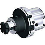
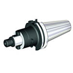
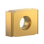
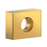
Produto semelhante ao:
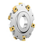
Narrow Slotting LN Series • Slotting width 6-12mm • Arbor Mount • Metric
Slot milling cutter for multiple materials.
Número de material1130615
ID do catálogo ISO160H16NS90LN12N06ID do catálogo ANSI160H16NS90LN12N06
- P Steel
- M Stainless Steel
- K Cast Iron
- S High-Temp Alloys
Abertura de canal: lateral com dimensões AE/AP
Sending to {{cadTool}} in progress...
Downloaded file will be available after import in the {{cadTool}} tool library.
- Visão geral
- Dados de aplicação
- Transferências
- Lado da máquina de peças compatíveis
- Lado da peça de peças compatíveis
- Peças de substituição
- Revisão
- Q&A
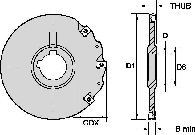
| Número de material | 1130615 |
| ID do catálogo ISO | 160H16NS90LN12N06 |
| ID do catálogo ANSI | 160H16NS90LN12N06 |
| [D1] Effective Cutting Diameter | 160 mm |
| [D1] Effective Cutting Diameter | 6.299 in |
| [D] Adapter / Shank / Bore Diameter | 40 mm |
| [D] Adapter / Shank / Bore Diameter | 1.5748 in |
| [D6] Hub Diameter | 63 mm |
| [D6] Hub Diameter | 2.4803 in |
| [BM] Cutting Width Minimum | 6 mm |
| [BM] Cutting Width Minimum | 0.2362 in |
| [CDX] Radial Maximum Depth of Cut | 46 mm |
| [CDX] Radial Maximum Depth of Cut | 1.811 in |
| [THUB] Hub Thickness | 12 mm |
| [THUB] Hub Thickness | 0.4724 in |
| Number of Inserts | 16 |
| [Z] Number of Flutes | 8 |
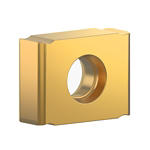
| Gage Insert | LNE_1235___ |
| Weight Kilograms | 1.1 |
Materiais das peças
- Steel
- Stainless Steel
- Cast Iron
- High-Temp Alloys
Usos e aplicações
Abertura de canal: lateral com dimensões AE/AP
Características e benefícios
- Easy cutting width adjustment through inserts with different thickness.
- Full side and face cutting.
- Two keyways for staggered mounting.
Criar solução para calcular avanços e velocidade
Após criar uma solução basta escolher o ícone Avanços & Velocidades e o nosso sistema irá fornecer recomendações. Pode personalizar as informações adicionando a sua máquina e especificações ou fazer ajustes utilizando os controlos deslizantes.
Avanços
Recommended Starting Feeds [mm]
| LN Slotting Series • Recommended Starting Feeds [mm/th] | |||||||||||||||
| Geometria do Inserto | Avanço por faca inicial recomendado (fz = mm/faca) em relação à % de engajamento radial (ae) | ||||||||||||||
| 5% | 10% | 20% | 30% | 40–100% | |||||||||||
| L | M | H | L | M | H | L | M | H | L | M | H | L | M | H | |
| LNEU… | 0.17 | 0.47 | 0.7 | 0.12 | 0.34 | 0.5 | 0.09 | 0.26 | 0.38 | 0.08 | 0.22 | 0.33 | 0.07 | 0.2 | 0.3 |
| LNEU…SGP | 0.23 | 0.52 | 0.81 | 0.17 | 0.37 | 0.58 | 0.13 | 0.28 | 0.43 | 0.11 | 0.24 | 0.38 | 0.1 | 0.22 | 0.35 |
| LNEQ... | 0.23 | 0.59 | 0.95 | 0.17 | 0.43 | 0.68 | 0.13 | 0.32 | 0.51 | 0.11 | 0.28 | 0.44 | 0.1 | 0.25 | 0.41 |
| L = Light Machining; M = Medium Machining; H = Heavy Machining NOTE: Use "Light Machining" values as starting feed rate. | |||||||||||||||
| LN Slotting Series • Recommended Starting Feeds [IPT] | |||||||||||||||
| Geometria do Inserto | Avanço por faca inicial recomendado (fz = mm/faca) em relação à % de engajamento radial (ae) | ||||||||||||||
| 5% | 10% | 20% | 30% | 40–100% | |||||||||||
| L | M | H | L | M | H | L | M | H | L | M | H | L | M | H | |
| LNEU… | 0.007 | 0.019 | 0.027 | 0.005 | 0.013 | 0.02 | 0.004 | 0.01 | 0.015 | 0.003 | 0.009 | 0.013 | 0.003 | 0.008 | 0.012 |
| LNEU…SGP | 0.009 | 0.02 | 0.032 | 0.007 | 0.015 | 0.023 | 0.005 | 0.011 | 0.017 | 0.004 | 0.01 | 0.015 | 0.004 | 0.009 | 0.014 |
| LNEQ... | 0.009 | 0.023 | 0.037 | 0.007 | 0.017 | 0.027 | 0.005 | 0.013 | 0.02 | 0.004 | 0.011 | 0.017 | 0.004 | 0.01 | 0.016 |
| L = Light Machining; M = Medium Machining; H = Heavy Machining NOTE: Use "Light Machining" values as starting feed rate. | |||||||||||||||
Velocidades
| LN Slotting Series • Recommended Starting Speed [m/min] | |||||||||||||||||||
| Classe | KC520M | KC725M | KCK15 | KCPK30 | KCK20B | KCPM40 | |||||||||||||
| Espessura média do cavaco hex mm | Mín. | Máx. | Mín. | Máx. | Mín. | Máx. | Mín. | Máx. | Mín. | Máx. | Mín. | Máx. | |||||||
| Grupo de material | Máx. | Início | Mín. | Máx. | Início | Mín. | Máx. | Início | Mín. | Máx. | Início | Mín. | Máx. | Início | Mín. | Máx. | Início | Mín. | |
| P | 1 | – | – | – | 260 | 230 | 215 | – | – | – | 455 | 395 | 370 | – | – | – | 295 | 260 | 245 |
| 2 | – | – | – | 220 | 190 | 160 | – | – | – | 280 | 255 | 230 | – | – | – | 250 | 215 | 180 | |
| 3 | – | – | – | 200 | 170 | 140 | – | – | – | 255 | 230 | 205 | – | – | – | 230 | 195 | 160 | |
| 4 | – | – | – | 180 | 150 | 120 | – | – | – | 225 | 185 | 160 | – | – | – | 205 | 170 | 135 | |
| 5 | – | – | – | 150 | 135 | 120 | – | – | – | 190 | 170 | 150 | – | – | – | 170 | 155 | 135 | |
| 6 | – | – | – | 130 | 100 | 80 | – | – | – | 160 | 135 | 110 | – | – | – | 150 | 115 | 90 | |
| M | 1 | – | – | – | 170 | 150 | 135 | – | – | – | 205 | 185 | 155 | – | – | – | 195 | 170 | 155 |
| 2 | – | – | – | 155 | 130 | 110 | – | – | – | 185 | 160 | 140 | – | – | – | 175 | 150 | 125 | |
| 3 | – | – | – | 115 | 100 | 80 | – | – | – | 145 | 130 | 115 | – | – | – | 130 | 115 | 90 | |
| K | 1 | 270 | 245 | 215 | – | – | – | 420 | 385 | 340 | 295 | 265 | 240 | 360 | 290 | 245 | – | – | – |
| 2 | 210 | 190 | 175 | – | – | – | 335 | 295 | 275 | 235 | 210 | 190 | 280 | 230 | 195 | – | – | – | |
| 3 | 175 | 160 | 145 | – | – | – | 280 | 250 | 230 | 195 | 175 | 160 | 210 | 175 | 140 | – | – | – | |
| N | 1 | – | – | – | – | – | – | – | – | – | – | – | – | – | – | – | – | – | – |
| 2 | – | – | – | – | – | – | – | – | – | – | – | – | – | – | – | – | – | – | |
| 3 | – | – | – | – | – | – | – | – | – | – | – | – | – | – | – | – | – | – | |
| S | 1 | – | – | – | 35 | 30 | 25 | – | – | – | – | – | – | – | – | – | 40 | 35 | 30 |
| 2 | – | – | – | 35 | 30 | 25 | – | – | – | – | – | – | – | – | – | 40 | 35 | 30 | |
| 3 | – | – | – | 45 | 35 | 25 | – | – | – | – | – | – | – | – | – | 50 | 40 | 30 | |
| 4 | – | – | – | 50 | 45 | 30 | – | – | – | 50 | 45 | 35 | – | – | – | 55 | 50 | 35 | |
| H | 1 | – | – | – | – | – | – | – | – | – | – | – | – | – | – | – | – | – | – |
| Recommended Starting Speed are pointing to 90° Shoulder Milling . Starting Speed for Face and Copy Milling can be Increased by 20 %. As the average chip thickness increases, speed should be decreased. Material groups P, M, K and H show recommended starting speeds for dry machining. For wet machining, reduce speed by 20%. Material groups N and S show recommended starting speeds for wet machining. Not recommended for dry machining. | |||||||||||||||||||
| LN Slotting Series • Recommended Starting Speed [SFM] | |||||||||||||||||||
| Classe | KC520M | KC725M | KCK15 | KCPK30 | KCK20B | KCPM40 | |||||||||||||
| Chip Thickness hex Inch | Mín. | Máx. | Mín. | Máx. | Mín. | Máx. | Mín. | Máx. | Mín. | Máx. | Mín. | Máx. | |||||||
| Grupo de material | Máx. | Início | Mín. | Máx. | Início | Mín. | Máx. | Início | Mín. | Máx. | Início | Mín. | Máx. | Início | Mín. | Máx. | Início | Mín. | |
| P | 1 | – | – | – | 855 | 755 | 705 | – | – | – | 1495 | 1295 | 1215 | – | – | – | 970 | 855 | 805 |
| 2 | – | – | – | 720 | 625 | 525 | – | – | – | 920 | 835 | 755 | – | – | – | 820 | 705 | 590 | |
| 3 | – | – | – | 655 | 560 | 460 | – | – | – | 835 | 755 | 675 | – | – | – | 755 | 640 | 525 | |
| 4 | – | – | – | 590 | 490 | 395 | – | – | – | 740 | 605 | 525 | – | – | – | 675 | 560 | 445 | |
| 5 | – | – | – | 490 | 445 | 395 | – | – | – | 625 | 560 | 490 | – | – | – | 560 | 510 | 445 | |
| 6 | – | – | – | 425 | 330 | 260 | – | – | – | 525 | 445 | 360 | – | – | – | 490 | 375 | 295 | |
| M | 1 | – | – | – | 560 | 490 | 445 | – | – | – | 675 | 605 | 510 | – | – | – | 640 | 560 | 510 |
| 2 | – | – | – | 510 | 425 | 360 | – | – | – | 605 | 525 | 460 | – | – | – | 575 | 490 | 410 | |
| 3 | – | – | – | 375 | 330 | 260 | – | – | – | 475 | 425 | 375 | – | – | – | 425 | 375 | 295 | |
| K | 1 | 885 | 805 | 705 | – | – | – | 1380 | 1265 | 1115 | 970 | 870 | 785 | 1180 | 950 | 805 | – | – | – |
| 2 | 690 | 625 | 575 | – | – | – | 1100 | 970 | 900 | 770 | 690 | 625 | 920 | 755 | 640 | – | – | – | |
| 3 | 575 | 525 | 475 | – | – | – | 920 | 820 | 755 | 640 | 575 | 525 | 690 | 575 | 460 | – | – | – | |
| N | 1 | – | – | – | – | – | – | – | – | – | – | – | – | – | – | – | – | – | – |
| 2 | – | – | – | – | – | – | – | – | – | – | – | – | – | – | – | – | – | – | |
| 3 | – | – | – | – | – | – | – | – | – | – | – | – | – | – | – | – | – | – | |
| S | 1 | – | – | – | 115 | 100 | 80 | – | – | – | – | – | – | – | – | – | 130 | 115 | 100 |
| 2 | – | – | – | 115 | 100 | 80 | – | – | – | – | – | – | – | – | – | 130 | 115 | 100 | |
| 3 | – | – | – | 150 | 115 | 80 | – | – | – | – | – | – | – | – | – | 165 | 130 | 100 | |
| 4 | – | – | – | 165 | 150 | 100 | – | – | – | 165 | 150 | 115 | – | – | – | 180 | 165 | 115 | |
| H | 1 | – | – | – | – | – | – | – | – | – | – | – | – | – | – | – | – | – | – |
| Recommended Starting Speed are pointing to 90° Shoulder Milling . Starting Speed for Face and Copy Milling can be Increased by 20 %. As the average chip thickness increases, speed should be decreased. Material groups P, M, K and H show recommended starting speeds for dry machining. For wet machining, reduce speed by 20%. Material groups N and S show recommended starting speeds for wet machining. Not recommended for dry machining. | |||||||||||||||||||
Seleção de insertos
| LN Slotting Series • Insert Selection Guide | ||||||
| Grupo de material | Usinagem leve | Usinagem geral | Usinagem pesada | |||
| – | (Geometria leve) | – | (Geometria reforçada) | |||
| – | resistência ao desgaste |  | tenacidade | |||
| – | Geometria | Classe | Geometria | Classe | Geometria | Classe |
| P1-P2 | LNEU… | KCPM40 | LNEU…SGP | KCPM40 | LNEQ... | KC725M |
| P3-P4 | LNEU… | KCPK30 | LNEU…SGP | KCPM40 | LNEQ... | KC725M |
| P5-P6 | LNEU… | KC725M | LNEU…SGP | KC725M | LNEQ... | KC725M |
| M1-M2 | LNEU… | KC725M | LNEU…SGP | KC725M | LNEQ... | KC725M |
| M3 | LNEU… | KCPM40 | LNEU…SGP | KCPM40 | LNEQ... | KC725M |
| K1-K2 | LNEU… | KCK20B | LNEU… | KCK20B | LNEQ... | KCK15 |
| K3 | LNEU… | KCK20B | LNEQ... | KCK20B | LNEQ... | KCK20B |
| N1-N2 | – | – | – | – | – | – |
| N3 | – | – | – | – | – | – |
| S1-S2 | LNEU… | KC725M | LNEU…SGP | KC725M | LNEQ... | KC725M |
| S3 | LNEU… | KCPK30 | LNEU…SGP | KCPM40 | LNEQ... | KC725M |
| S4 | LNEU… | KC725M | LNEU…SGP | KC725M | LNEQ... | KC725M |
| H1 | – | – | – | – | – | – |
I have read and accepted the Terms & Conditions of use
CAD Drawings Models
Can’t find the file type you’re looking for?
Product data
