Producto similar a:
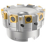
Fix-Perfect™ 90° • Shell Mill • Metric
Face Mill • Cast Iron Machining
Número de material1501653
Referencia ISO63A08RP90SP12CFPReferencia ANSI63A08RP90SP12CFP
- P Acero
- M Acero inoxidable
- K Fundición
- S Aleaciones de alta temperatura
Planeado
Fresado lateral/Fresado en escuadra: Placa cuadrada
Fresado — Con refrigeración interna
Fresado — lateral y planeado
Sending to {{cadTool}} in progress...
Downloaded file will be available after import in the {{cadTool}} tool library.
- Información general
- Datos de aplicación
- Descargas
- Piezas compatibles Lado máquina
- Piezas compatibles Lado de la pieza
- Piezas de recambio
- Comentarios
- Preguntas y Respuestas
| Número de material | 1501653 |
| Referencia ISO | 63A08RP90SP12CFP |
| Referencia ANSI | 63A08RP90SP12CFP |
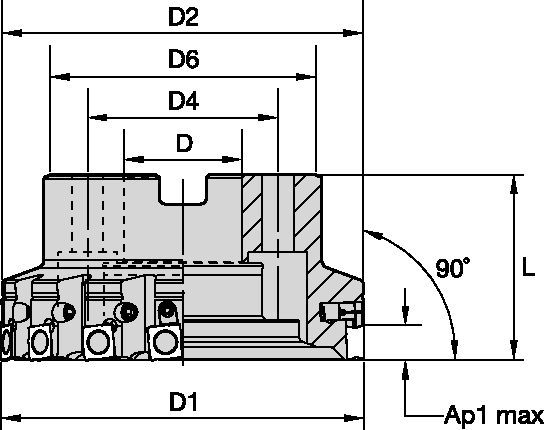
| Diámetro de corte efectivo [D1] | 63 mm |
| Diámetro de corte efectivo [D1] | 2.4803 in |
| Adaptador/Mango/Diá int [D] | 22 mm |
| Adaptador/Mango/Diá int [D] | 0.8661 in |
| Diámetro de cuerpo máximo [D2] | 61.4 mm |
| Diámetro de cuerpo máximo [D2] | 2.4173 in |
| Diámetro de núcleo [D6] | 51 mm |
| Diámetro de núcleo [D6] | 2.0079 in |
| Longitud total [L] | 40 mm |
| Longitud total [L] | 1.575 in |
| 1.ª profundidad de corte máxima [AP1MAX] | 6 mm |
| 1.ª profundidad de corte máxima [AP1MAX] | 0.236 in |
| Número de plaquitas | 8 |
| Número de plaquitas ajustables | 0 |
| Peso en kilogramos | 0.6 |
| RPM máx. | 5000 |
Materiales de la pieza de trabajo
- Acero
- Acero inoxidable
- Fundición
- Aleaciones de alta temperatura
Uses and application
Planeado
Fresado lateral/Fresado en escuadra: Placa cuadrada
Fresado — Con refrigeración interna
Fresado — lateral y planeado
Features and benefits
- Milling cutters for roughing applications in cast iron and compacted graphite iron (CGI).
- High feed rates through tangentially mounted inserts.
- Pocket design protects non-engaged cutting edges.
Crear una solución para calcular la velocidad y el avance
Después de crear una solución, sólo tiene que elegir el icono Avance y Velocidad y nuestro sistema le ofrecerá recomendaciones. Puede personalizar la información añadiendo su máquina y especificaciones o realizar ajustes utilizando los controles deslizantes.
Feeds
Avances iniciales recomendados [mm]
| Mecanizado ligero | Aplicaciones generales | Mecanizado intensivo |
| Geometría de plaquita | Avance inicial recomendado por diente (Fz) en relación con % de contacto radial (ae) | Geometría de plaquita | ||||||||||||||
| 5% | 10% | 20% | 30% | 40–100% | ||||||||||||
| .E..GPB | 0,12 | 0,46 | 0,82 | 0,08 | 0,33 | 0,59 | 0,06 | 0,25 | 0,44 | 0,06 | 0,22 | 0,38 | 0,05 | 0,20 | 0,35 | .E..GPB |
| .T..GPB | 0,23 | 0,59 | 0,95 | 0,17 | 0,43 | 0,68 | 0,13 | 0,32 | 0,51 | 0,11 | 0,28 | 0,44 | 0,10 | 0,25 | 0,41 | .T..GPB |
| .S..GPB | 0,23 | 0,59 | 0,95 | 0,17 | 0,43 | 0,68 | 0,13 | 0,32 | 0,51 | 0,11 | 0,28 | 0,44 | 0,10 | 0,25 | 0,41 | .S..GPB |
Avances iniciales recomendados [mm]
| Geometría de plaquita | Avance inicial recomendado por diente (Fz) en relación con % de contacto radial (ae) | Geometría de plaquita | ||||||||||||||
| 5% | 10% | 20% | 30% | 40–100% | ||||||||||||
| .E..GP | 0,12 | 0,46 | 0,82 | 0,08 | 0,33 | 0,59 | 0,06 | 0,25 | 0,44 | 0,06 | 0,22 | 0,38 | 0,05 | 0,20 | 0,35 | .E..GP |
| .S..GP | 0,23 | 0,59 | 0,95 | 0,17 | 0,43 | 0,68 | 0,13 | 0,32 | 0,51 | 0,11 | 0,28 | 0,44 | 0,10 | 0,25 | 0,41 | .S..GP |
| Mecanizado ligero | Aplicaciones generales | Mecanizado intensivo |
Speeds
Velocidades iniciales recomendadas (m/min)
| Grupo de materiales | KB1340 | KC520M | KCK15 | KTPK20 | KCPK30 | KY3500 | |||||||||||||
| P | 1 | – | – | – | – | – | – | – | – | – | – | – | – | – | – | – | – | – | – |
| 2 | – | – | – | – | – | – | – | – | – | – | – | – | – | – | – | – | – | – | |
| 3 | – | – | – | – | – | – | – | – | – | – | – | – | – | – | – | – | – | – | |
| 4 | – | – | – | – | – | – | – | – | – | – | – | – | – | – | – | – | – | – | |
| 5 | – | – | – | – | – | – | – | – | – | – | – | – | – | – | – | – | – | – | |
| 6 | – | – | – | – | – | – | – | – | – | – | – | – | – | – | – | – | – | – | |
| M | 1 | – | – | – | – | – | – | – | – | – | – | – | – | – | – | – | – | – | – |
| 2 | – | – | – | – | – | – | – | – | – | – | – | – | – | – | – | – | – | – | |
| 3 | – | – | – | – | – | – | – | – | – | – | – | – | – | – | – | – | – | – | |
| K | 1 | 1370 | 915 | 490 | 270 | 245 | 215 | 420 | 385 | 340 | 230 | 195 | 160 | 295 | 265 | 240 | 805 | 730 | 650 |
| 2 | – | – | – | 210 | 190 | 175 | 335 | 295 | 275 | 185 | 150 | 130 | 235 | 210 | 190 | 635 | 570 | 530 | |
| 3 | – | – | – | 175 | 160 | 145 | 280 | 250 | 230 | 150 | 130 | 105 | 195 | 175 | 160 | 535 | 475 | 435 | |
| N | 1–2 | – | – | – | – | – | – | – | – | – | – | – | – | – | – | – | – | – | – |
| 3 | – | – | – | – | – | – | – | – | – | – | – | – | – | – | – | – | – | – | |
| S | 1 | – | – | – | – | – | – | – | – | – | – | – | – | – | – | – | – | – | – |
| 2 | – | – | – | – | – | – | – | – | – | – | – | – | – | – | – | – | – | – | |
| 3 | – | – | – | – | – | – | – | – | – | – | – | – | – | – | – | – | – | – | |
| 4 | – | – | – | – | – | – | – | – | – | – | – | – | – | – | – | – | – | – | |
| H | 1 | – | – | – | – | – | – | – | – | – | – | – | – | – | – | – | – | – | – |
Velocidades iniciales recomendadas (m/min)
| Grupo de materiales | KB1340 | KC520M | KCK15 | KCPK30 | KY3500 | |||||||||||
| P | 1 | – | – | – | – | – | – | – | – | – | – | – | – | – | – | – |
| 2 | – | – | – | – | – | – | – | – | – | – | – | – | – | – | – | |
| 3 | – | – | – | – | – | – | – | – | – | – | – | – | – | – | – | |
| 4 | – | – | – | – | – | – | – | – | – | – | – | – | – | – | – | |
| 5 | – | – | – | – | – | – | – | – | – | – | – | – | – | – | – | |
| 6 | – | – | – | – | – | – | – | – | – | – | – | – | – | – | – | |
| M | 1 | – | – | – | – | – | – | – | – | – | – | – | – | – | – | – |
| 2 | – | – | – | – | – | – | – | – | – | – | – | – | – | – | – | |
| 3 | – | – | – | – | – | – | – | – | – | – | – | – | – | – | – | |
| K | 1 | 1370 | 915 | 490 | 270 | 245 | 215 | 420 | 385 | 340 | 295 | 265 | 240 | 805 | 730 | 650 |
| 2 | – | – | – | 210 | 190 | 175 | 335 | 295 | 275 | 235 | 210 | 190 | 635 | 570 | 530 | |
| 3 | – | – | – | 175 | 160 | 145 | 280 | 250 | 230 | 195 | 175 | 160 | 535 | 475 | 435 | |
| N | 1–2 | – | – | – | – | – | – | – | – | – | – | – | – | – | – | – |
| 3 | – | – | – | – | – | – | – | – | – | – | – | – | – | – | – | |
| S | 1 | – | – | – | – | – | – | – | – | – | – | – | – | – | – | – |
| 2 | – | – | – | – | – | – | – | – | – | – | – | – | – | – | – | |
| 3 | – | – | – | – | – | – | – | – | – | – | – | – | – | – | – | |
| 4 | – | – | – | – | – | – | – | – | – | – | – | – | – | – | – | |
| H | 1 | – | – | – | – | – | – | – | – | – | – | – | – | – | – | – |
Datos de aplicación
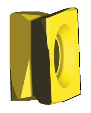
Conjunto de plaquitas para fresas de fundición Fix-Perfect™
| roughing | procedures | roughing/finishing | |||
 |  |  |  | ||
| insert seat | insert seat | ||||
| estándar | adjustable | estándar | adjustable | ||
| ― | 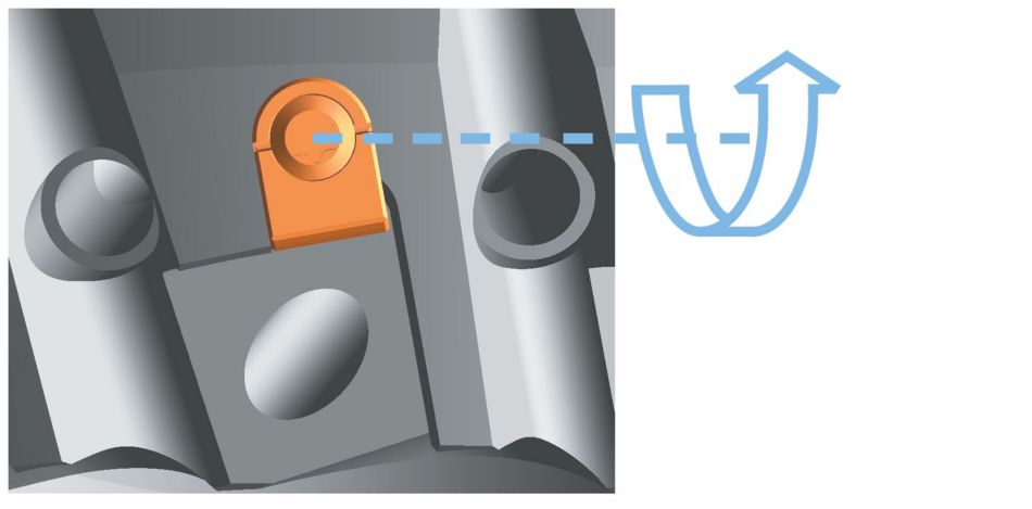 | 1 | Reset adjusting element T x T9 | ― |  |
 | 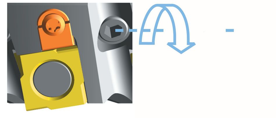 | 2 | insert roughing insert tighten SW 3 MAn = 5 Nm |  | ― |
| ― |  | 3 | tighten adjusting element gently | ― | ― |
| 4 | insert finishing insert and pre-tighten SW 3 M VG = 1 Nm | ― |  | ||
| 5 | the finishing insert is positioned 0,04mm in front of the highest roughing insert | ― | 0,04 mm (0.0016 pulg.) | ||
| 6 | tighten the finishing insert MAn = 5 Nm | ― |  | ||
Insert Selection
Guía para la selección de plaquitas
| Grupo de materiales | Mecanizado ligero | Aplicaciones generales | Mecanizado intensivo | |||
| (Geometría ligera) | – | (Geometría fuerte) | ||||
| resistencia |  | tenacidad | ||||
| Geometría | Calidad | Geometría | Calidad | Geometría | Calidad | |
| P1–P2 | – | – | – | – | – | – |
| P3–P4 | – | – | – | – | – | – |
| P5–P6 | – | – | – | – | – | – |
| M1–M2 | – | – | – | – | – | – |
| M3 | – | – | – | – | – | – |
| K1–K2 | .E..GPB | KC520M | .E..GPB | KCK15 | .S..GPB | KCK15 |
| K3 | .E..GPB | KC520M | .E..GPB | KCK15 | .S..GPB | KCK15 |
| N1–N2 | – | – | – | – | – | – |
| N3 | – | – | – | – | – | – |
| S1–S2 | – | – | – | – | – | – |
| S3 | – | – | – | – | – | – |
| S4 | – | – | – | – | – | – |
| H1 | – | – | – | – | – | – |
Guía para la selección de plaquitas
| Grupo de materiales | Mecanizado ligero | Aplicaciones generales | Mecanizado intensivo | |||
| (Geometría ligera) | – | (Geometría fuerte) | ||||
| resistencia |  | tenacidad | ||||
| Geometría | Calidad | Geometría | Calidad | Geometría | Calidad | |
| P1–P2 | – | – | – | – | – | – |
| P3–P4 | – | – | – | – | – | – |
| P5–P6 | – | – | – | – | – | – |
| M1–M2 | – | – | – | – | – | – |
| M3 | – | – | – | – | – | – |
| K1–K2 | .E..GP | KC520M | .E..GP | KCK15 | .E..GP | KCK15 |
| K3 | .E..GP | KC520M | .E..GP | KCK15 | .S..GP | KCPK30 |
| N1–N2 | – | – | – | – | – | – |
| N3 | – | – | – | – | – | – |
| S1–S2 | – | – | – | – | – | – |
| S3 | – | – | – | – | – | – |
| S4 | – | – | – | – | – | – |
| H1 | – | – | – | – | – | – |
I have read and accepted the Terms & Conditions of use
CAD Drawings Models
Can’t find the file type you’re looking for?
Product data
