Produto semelhante ao:
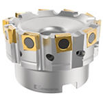
Fix-Perfect™ 90° • Shell Mill • Metric
Face Mill • Cast Iron Machining
Número de material1503012
ID do catálogo ISO63A06RP90SP12CFPID do catálogo ANSI63A06RP90SP12CFP
- P Steel
- M Stainless Steel
- K Cast Iron
- S High-Temp Alloys
Fresamento de face
Fresamento lateral/fresamento de canto: topo reto
Fresamento — Refrigeração interna
Fresamento — Lateral e de face
Sending to {{cadTool}} in progress...
Downloaded file will be available after import in the {{cadTool}} tool library.
- Visão geral
- Dados de aplicação
- Transferências
- Lado da máquina de peças compatíveis
- Lado da peça de peças compatíveis
- Peças de substituição
- Revisão
- Q&A
| Número de material | 1503012 |
| ID do catálogo ISO | 63A06RP90SP12CFP |
| ID do catálogo ANSI | 63A06RP90SP12CFP |
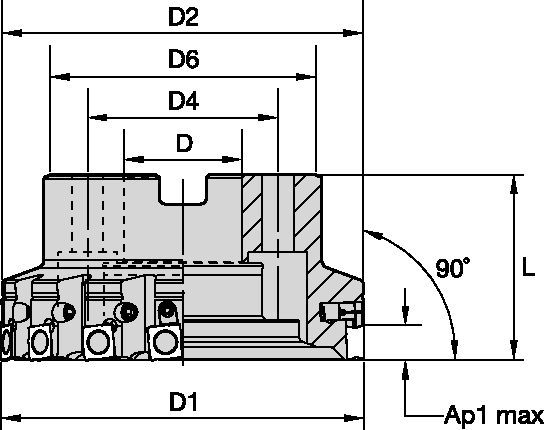
| [D1] Effective Cutting Diameter | 63 mm |
| [D1] Effective Cutting Diameter | 2.48 in |
| [D] Adapter / Shank / Bore Diameter | 22 mm |
| [D] Adapter / Shank / Bore Diameter | .8661 in |
| [D2] Maximum Body Diameter | 61.4 mm |
| [D2] Maximum Body Diameter | 2.417 in |
| [D6] Hub Diameter | 51 mm |
| [D6] Hub Diameter | 2.007 in |
| [L] Overall Length | 40 mm |
| [L] Overall Length | 1.575 in |
| [AP1MAX] 1st Maximum Cutting Depth | 6 mm |
| [AP1MAX] 1st Maximum Cutting Depth | .236 in |
| Number of Inserts | 6 |
| Number of Adjustable Inserts | 0 |
| Weight Kilograms | 0.59 |
| Max RPM | 5000 |
Materiais das peças
- Steel
- Stainless Steel
- Cast Iron
- High-Temp Alloys
Usos e aplicações
Fresamento de face
Fresamento lateral/fresamento de canto: topo reto
Fresamento — Refrigeração interna
Fresamento — Lateral e de face
Características e benefícios
- Milling cutters for roughing applications in cast iron and compacted graphite iron (CGI).
- High feed rates through tangentially mounted inserts.
- Pocket design protects non-engaged cutting edges.
Criar solução para calcular avanços e velocidade
Após criar uma solução basta escolher o ícone Avanços & Velocidades e o nosso sistema irá fornecer recomendações. Pode personalizar as informações adicionando a sua máquina e especificações ou fazer ajustes utilizando os controlos deslizantes.
Seleção de insertos
Guia de seleção de insertos
| Grupo de material | Usinagem leve | Usinagem geral | Usinagem pesada | |||
| (Geometria leve) | – | (Geometria reforçada) | ||||
| resistência ao desgaste |  | tenacidade | ||||
| Geometria | Classe | Geometria | Classe | Geometria | Classe | |
| P1–P2 | – | – | – | – | – | – |
| P3–P4 | – | – | – | – | – | – |
| P5–P6 | – | – | – | – | – | – |
| M1–M2 | – | – | – | – | – | – |
| M3 | – | – | – | – | – | – |
| K1–K2 | .E..GPB | KC520M | .E..GPB | KCK15 | .S..GPB | KCK15 |
| K3 | .E..GPB | KC520M | .E..GPB | KCK15 | .S..GPB | KCK15 |
| N1–N2 | – | – | – | – | – | – |
| N3 | – | – | – | – | – | – |
| S1–S2 | – | – | – | – | – | – |
| S3 | – | – | – | – | – | – |
| S4 | – | – | – | – | – | – |
| H1 | – | – | – | – | – | – |
Guia de seleção de insertos
| Grupo de material | Usinagem leve | Usinagem geral | Usinagem pesada | |||
| (Geometria leve) | – | (Geometria reforçada) | ||||
| resistência ao desgaste |  | tenacidade | ||||
| Geometria | Classe | Geometria | Classe | Geometria | Classe | |
| P1–P2 | – | – | – | – | – | – |
| P3–P4 | – | – | – | – | – | – |
| P5–P6 | – | – | – | – | – | – |
| M1–M2 | – | – | – | – | – | – |
| M3 | – | – | – | – | – | – |
| K1–K2 | .E..GP | KC520M | .E..GP | KCK15 | .E..GP | KCK15 |
| K3 | .E..GP | KC520M | .E..GP | KCK15 | .S..GP | KCPK30 |
| N1–N2 | – | – | – | – | – | – |
| N3 | – | – | – | – | – | – |
| S1–S2 | – | – | – | – | – | – |
| S3 | – | – | – | – | – | – |
| S4 | – | – | – | – | – | – |
| H1 | – | – | – | – | – | – |
Avanços
Avanços iniciais recomendados [mm]
| Usinagem leve | Usinagem geral | Usinagem pesada |
| Geometria do Inserto | Avanço por faca inicial recomendado (fz = mm/faca) em relação à % de engajamento radial (ae) | Geometria do Inserto | ||||||||||||||
| 5% | 10% | 20% | 30% | 40–100% | ||||||||||||
| .E..GPB | 0,12 | 0,46 | 0,82 | 0,08 | 0,33 | 0,59 | 0,06 | 0,25 | 0,44 | 0,06 | 0,22 | 0,38 | 0,05 | 0,20 | 0,35 | .E..GPB |
| .T..GPB | 0,23 | 0,59 | 0,95 | 0,17 | 0,43 | 0,68 | 0,13 | 0,32 | 0,51 | 0,11 | 0,28 | 0,44 | 0,10 | 0,25 | 0,41 | .T..GPB |
| .S..GPB | 0,23 | 0,59 | 0,95 | 0,17 | 0,43 | 0,68 | 0,13 | 0,32 | 0,51 | 0,11 | 0,28 | 0,44 | 0,10 | 0,25 | 0,41 | .S..GPB |
Avanços iniciais recomendados [mm]
| Geometria do Inserto | Avanço por faca inicial recomendado (fz = mm/faca) em relação à % de engajamento radial (ae) | Geometria do Inserto | ||||||||||||||
| 5% | 10% | 20% | 30% | 40–100% | ||||||||||||
| .E..GP | 0,12 | 0,46 | 0,82 | 0,08 | 0,33 | 0,59 | 0,06 | 0,25 | 0,44 | 0,06 | 0,22 | 0,38 | 0,05 | 0,20 | 0,35 | .E..GP |
| .S..GP | 0,23 | 0,59 | 0,95 | 0,17 | 0,43 | 0,68 | 0,13 | 0,32 | 0,51 | 0,11 | 0,28 | 0,44 | 0,10 | 0,25 | 0,41 | .S..GP |
| Usinagem leve | Usinagem geral | Usinagem pesada |
Velocidades
Velocidades recomendadas iniciais [m/min]
| Grupo de material | KB1340 | KC520M | KCK15 | KTPK20 | KCPK30 | KY3500 | |||||||||||||
| P | 1 | – | – | – | – | – | – | – | – | – | – | – | – | – | – | – | – | – | – |
| 2 | – | – | – | – | – | – | – | – | – | – | – | – | – | – | – | – | – | – | |
| 3 | – | – | – | – | – | – | – | – | – | – | – | – | – | – | – | – | – | – | |
| 4 | – | – | – | – | – | – | – | – | – | – | – | – | – | – | – | – | – | – | |
| 5 | – | – | – | – | – | – | – | – | – | – | – | – | – | – | – | – | – | – | |
| 6 | – | – | – | – | – | – | – | – | – | – | – | – | – | – | – | – | – | – | |
| M | 1 | – | – | – | – | – | – | – | – | – | – | – | – | – | – | – | – | – | – |
| 2 | – | – | – | – | – | – | – | – | – | – | – | – | – | – | – | – | – | – | |
| 3 | – | – | – | – | – | – | – | – | – | – | – | – | – | – | – | – | – | – | |
| K | 1 | 1370 | 915 | 490 | 270 | 245 | 215 | 420 | 385 | 340 | 230 | 195 | 160 | 295 | 265 | 240 | 805 | 730 | 650 |
| 2 | – | – | – | 210 | 190 | 175 | 335 | 295 | 275 | 185 | 150 | 130 | 235 | 210 | 190 | 635 | 570 | 530 | |
| 3 | – | – | – | 175 | 160 | 145 | 280 | 250 | 230 | 150 | 130 | 105 | 195 | 175 | 160 | 535 | 475 | 435 | |
| N | 1–2 | – | – | – | – | – | – | – | – | – | – | – | – | – | – | – | – | – | – |
| 3 | – | – | – | – | – | – | – | – | – | – | – | – | – | – | – | – | – | – | |
| S | 1 | – | – | – | – | – | – | – | – | – | – | – | – | – | – | – | – | – | – |
| 2 | – | – | – | – | – | – | – | – | – | – | – | – | – | – | – | – | – | – | |
| 3 | – | – | – | – | – | – | – | – | – | – | – | – | – | – | – | – | – | – | |
| 4 | – | – | – | – | – | – | – | – | – | – | – | – | – | – | – | – | – | – | |
| H | 1 | – | – | – | – | – | – | – | – | – | – | – | – | – | – | – | – | – | – |
Velocidades recomendadas iniciais [m/min]
| Grupo de material | KB1340 | KC520M | KCK15 | KCPK30 | KY3500 | |||||||||||
| P | 1 | – | – | – | – | – | – | – | – | – | – | – | – | – | – | – |
| 2 | – | – | – | – | – | – | – | – | – | – | – | – | – | – | – | |
| 3 | – | – | – | – | – | – | – | – | – | – | – | – | – | – | – | |
| 4 | – | – | – | – | – | – | – | – | – | – | – | – | – | – | – | |
| 5 | – | – | – | – | – | – | – | – | – | – | – | – | – | – | – | |
| 6 | – | – | – | – | – | – | – | – | – | – | – | – | – | – | – | |
| M | 1 | – | – | – | – | – | – | – | – | – | – | – | – | – | – | – |
| 2 | – | – | – | – | – | – | – | – | – | – | – | – | – | – | – | |
| 3 | – | – | – | – | – | – | – | – | – | – | – | – | – | – | – | |
| K | 1 | 1370 | 915 | 490 | 270 | 245 | 215 | 420 | 385 | 340 | 295 | 265 | 240 | 805 | 730 | 650 |
| 2 | – | – | – | 210 | 190 | 175 | 335 | 295 | 275 | 235 | 210 | 190 | 635 | 570 | 530 | |
| 3 | – | – | – | 175 | 160 | 145 | 280 | 250 | 230 | 195 | 175 | 160 | 535 | 475 | 435 | |
| N | 1–2 | – | – | – | – | – | – | – | – | – | – | – | – | – | – | – |
| 3 | – | – | – | – | – | – | – | – | – | – | – | – | – | – | – | |
| S | 1 | – | – | – | – | – | – | – | – | – | – | – | – | – | – | – |
| 2 | – | – | – | – | – | – | – | – | – | – | – | – | – | – | – | |
| 3 | – | – | – | – | – | – | – | – | – | – | – | – | – | – | – | |
| 4 | – | – | – | – | – | – | – | – | – | – | – | – | – | – | – | |
| H | 1 | – | – | – | – | – | – | – | – | – | – | – | – | – | – | – |
Dados de aplicação
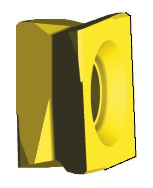
Montagem do inserto para fresas de ferro fundido Fix-Perfect™
| desbaste | procedures | roughing/finishing | |||
 |  |  |  | ||
| insert seat | insert seat | ||||
| padrão | adjustable | padrão | adjustable | ||
| ― | 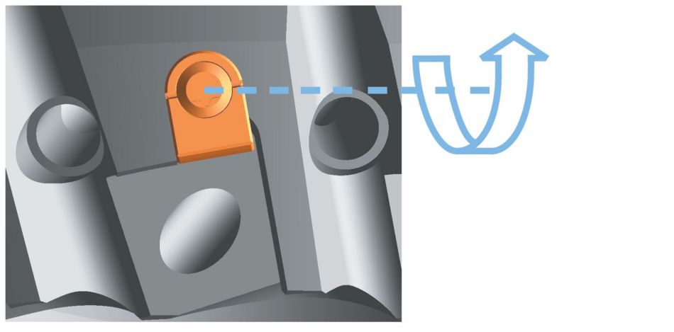 | 1 | Reset adjusting element T x T9 | ― |  |
 | 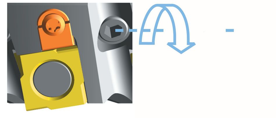 | 2 | insert roughing insert tighten SW 3 MAn = 5 Nm |  | ― |
| ― |  | 3 | tighten adjusting element gently | ― | ― |
| 4 | insert finishing insert and pre-tighten SW 3 M VG = 1 Nm | ― |  | ||
| 5 | the finishing insert is positioned 0,04mm in front of the highest roughing insert | ― | 0,04mm (.0016in.) | ||
| 6 | tighten the finishing insert MAn = 5 Nm | ― |  | ||
CAD Drawings Models
Can’t find the file type you’re looking for?
Product data
I have read and accepted the Terms & Conditions of use
