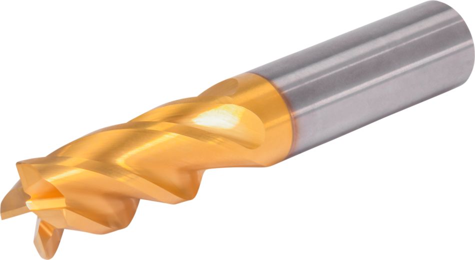
GOmill™ PRO • Ball Nose • 4 Flutes • Necked • Plain Shank • Metric
GOmill™ PRO • Ball Nose • 4 Flutes • Necked • Plain Shank • Metric
Solid Carbide End Mill for Roughing and Finishing of Multiple Materials
제품 번호109353097
일반적인 표현
모든 가격 옵션을 알아보려면 당사 영업팀에 문의하세요.
특징 및 장점
- Unequal flute spacing for better vibration control and tool life.
- Multilayer TiN/TiALN coating for high performance at medium-high cutting on steels, stainless steels and cast iron.
- Ideal for shops working in the general engineering, transportation, energy and medical industries.
- Designed for side and shoulder milling, helical milling, pocketing, slotting and ramping.
헬리컬 밀링
램핑: 블랭크
슬로팅: 볼 노즈
사이드 밀링/숄더 밀링: 볼 노즈
3D 프로파일링
Corner Style: Ball Nose
섕크 — 원통형 일반
| Angle of engagement (phi°) relative to cutting width (Ae) |  | ||||||||||
| ae | 2% | 4% | 5% | 8% | 10% | 12% | 20% | 30% | 40% | 50% | 100% |
| phi - angle of engagement | 16.26 | 23.07 | 25.84 | 32.86 | 36.87 | 40.54 | 53.13 | 66.42 | 78.46 | 90.00 | 180.00 |
| Adjustment factors for speed (Vc) and feed (Fz) • Metric | |||||||||||
| Ae/D1 | 2% | 4% | 5% | 8% | 10% | 12% | 20% | 30% | 40% | 50% | 100% |
| Kv | 2.1 - 3.6 | 1.6 - 3 | 1.6 - 2.5 | 1.6 | 1.4 | 1.38 | 1.3 | 1.2 | 1.1 | 1 | 1 |
| KFz | 3.58 | 2.56 | 2.3 | 1.84 | 1.67 | 1.54 | 1.25 | 1.09 | 1.02 | 1 | 0.9 |
| Note: Identify the radial engagement per percentage of the tool diameter (Ae/D1). That column will give you the factor to multiply the Base SMF and Base IPT on the Speed and Feed original table Kv = Factor to multiply the Speed by KFz = Factor to multiply the Feed by | |||||||||||
| To calculate application specific cutting data, please use Kv coefficient, and KFz from tables for adaption of cutting speeds and feeds respectively: Vc new = Vc * Kv IPT new = IPT * KFz | Sample Calculation Material: P5 D1: 14.0 mm Ae: 20% of D1 Recommended Speed Vc : 80 m/min Recommended Feed Fz: 0.063 mm/th Adjustment coefficient Kv : 1.30 Adjustment coefficient KFz : 1.25 | Final cutting data recommendation: Vc new = 80 * 1.30 = 104 m/min Fz new = 0.063 * 1.30 = 0.079 mm/th | |||||||||
| GOmill™ PRO • Regular • Recommended Starting Speed and Feed [Metric] | ||||||||||||||||||||
 |  |  | ||||||||||||||||||
| KCU25 | 날당 이송 fz(fz = mm/th) 는 사이드 밀링(A)용입니다. 슬로팅(B)의 경우 fz를 20%까지 줄이십시오. | |||||||||||||||||||
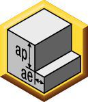
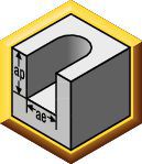
| 사이드 밀링 | 슬로팅 | 가공 속도 | D1 | |||||||||||||||||
| 소재 그룹 | ap | ae | ap | 최소 | 초기값 | 최대 | mm | 2,0 | 3,0 | 4,0 | 5,0 | 6,0 | 8,0 | 10,0 | 12,0 | 14,0 | 16,0 | 18,0 | 20,0 | 25,0 |
| P0 | Ap1 Max | 0,4 x D1 | 1,0 x D1 | 150 | 175 | 200 | fz | 0.014 | 0.021 | 0.028 | 0.036 | 0.044 | 0.060 | 0.072 | 0.083 | 0.092 | 0.101 | 0.108 | 0.114 | 0.124 |
| P1 | Ap1 Max | 0,4 x D1 | 1,0 x D1 | 150 | 175 | 200 | fz | 0.014 | 0.021 | 0.028 | 0.036 | 0.044 | 0.060 | 0.072 | 0.083 | 0.092 | 0.101 | 0.108 | 0.114 | 0.124 |
| P2 | Ap1 Max | 0,4 x D1 | 1,0 x D1 | 140 | 165 | 190 | fz | 0.014 | 0.021 | 0.028 | 0.036 | 0.044 | 0.060 | 0.072 | 0.083 | 0.092 | 0.101 | 0.108 | 0.114 | 0.124 |
| P3 | Ap1 Max | 0,4 x D1 | 1,0 x D1 | 120 | 140 | 160 | fz | 0.011 | 0.017 | 0.023 | 0.030 | 0.036 | 0.050 | 0.061 | 0.070 | 0.079 | 0.087 | 0.095 | 0.101 | 0.114 |
| P4 | Ap1 Max | 0,4 x D1 | 0,75 x D1 | 90 | 120 | 150 | fz | 0.010 | 0.016 | 0.021 | 0.027 | 0.033 | 0.045 | 0.054 | 0.062 | 0.070 | 0.077 | 0.083 | 0.088 | 0.098 |
| P5 | Ap1 Max | 0,4 x D1 | 1,0 x D1 | 60 | 80 | 100 | fz | 0.009 | 0.014 | 0.019 | 0.024 | 0.029 | 0.040 | 0.048 | 0.056 | 0.063 | 0.070 | 0.076 | 0.081 | 0.091 |
| P6 | Ap1 Max | 0,4 x D1 | 0,75 x D1 | 50 | 63 | 75 | fz | 0.008 | 0.012 | 0.016 | 0.020 | 0.025 | 0.034 | 0.040 | 0.047 | 0.052 | 0.057 | 0.061 | 0.065 | 0.071 |
| M1 | Ap1 Max | 0,4 x D1 | 1,0 x D1 | 90 | 103 | 115 | fz | 0.011 | 0.017 | 0.023 | 0.030 | 0.036 | 0.050 | 0.061 | 0.070 | 0.079 | 0.087 | 0.095 | 0.101 | 0.114 |
| M2 | Ap1 Max | 0,4 x D1 | 1,0 x D1 | 60 | 70 | 80 | fz | 0.009 | 0.014 | 0.019 | 0.024 | 0.029 | 0.040 | 0.048 | 0.056 | 0.063 | 0.070 | 0.076 | 0.081 | 0.091 |
| M3 | Ap1 Max | 0,4 x D1 | 1,0 x D1 | 60 | 65 | 70 | fz | 0.008 | 0.012 | 0.016 | 0.020 | 0.025 | 0.034 | 0.040 | 0.047 | 0.052 | 0.057 | 0.061 | 0.065 | 0.071 |
| K1 | Ap1 Max | 0,4 x D1 | 1,0 x D1 | 120 | 135 | 150 | fz | 0.014 | 0.021 | 0.028 | 0.036 | 0.044 | 0.060 | 0.072 | 0.083 | 0.092 | 0.101 | 0.108 | 0.114 | 0.124 |
| K2 | Ap1 Max | 0,4 x D1 | 1,0 x D1 | 110 | 125 | 140 | fz | 0.011 | 0.017 | 0.023 | 0.030 | 0.036 | 0.050 | 0.061 | 0.070 | 0.079 | 0.087 | 0.095 | 0.101 | 0.114 |
| K3 | Ap1 Max | 0,4 x D1 | 1,0 x D1 | 110 | 120 | 130 | fz | 0.009 | 0.014 | 0.019 | 0.024 | 0.029 | 0.040 | 0.048 | 0.056 | 0.063 | 0.070 | 0.076 | 0.081 | 0.091 |
| S1 | Ap1 Max | 0,4 x D1 | 0,3 x D1 | 50 | 70 | 90 | fz | 0.011 | 0.017 | 0.023 | 0.030 | 0.036 | 0.050 | 0.061 | 0.070 | 0.079 | 0.087 | 0.095 | 0.101 | 0.114 |
| S2 | Ap1 Max | 0,4 x D1 | 0,3 x D1 | 25 | 38 | 50 | fz | 0.006 | 0.009 | 0.013 | 0.016 | 0.019 | 0.026 | 0.032 | 0.037 | 0.042 | 0.046 | 0.050 | 0.054 | 0.061 |
| S3 | Ap1 Max | 0,4 x D1 | 1,0 x D1 | 25 | 33 | 40 | fz | 0.006 | 0.009 | 0.013 | 0.016 | 0.019 | 0.026 | 0.032 | 0.037 | 0.042 | 0.046 | 0.050 | 0.054 | 0.061 |
| S4 | Ap1 Max | 0,4 x D1 | 1,0 x D1 | 50 | 55 | 60 | fz | 0.007 | 0.011 | 0.016 | 0.021 | 0.026 | 0.037 | 0.045 | 0.052 | 0.058 | 0.064 | 0.069 | 0.074 | 0.084 |
| H1 | Ap1 Max | 0,4 x D1 | 0,75 x D1 | 80 | 110 | 140 | fz | 0.010 | 0.016 | 0.021 | 0.027 | 0.033 | 0.045 | 0.054 | 0.062 | 0.070 | 0.077 | 0.083 | 0.088 | 0.098 |
| H2 | Ap1 Max | 0,4 x D1 | 0,5 x D1 | 70 | 95 | 120 | fz | 0.008 | 0.012 | 0.016 | 0.020 | 0.025 | 0.034 | 0.040 | 0.047 | 0.052 | 0.057 | 0.061 | 0.065 | 0.071 |
| Lower value of cuting speed is used for high stock removal applications or for higher hardness (machinability) within group. Higher value of cuting speed is used for finishing applications or for lower hardness (machinability) within group. Above parameters are based on ideal conditions. For smaller taper machining centers, please adjust parameters accordiongly on diameters greater than 12mm. For better surface finish reduce feed per tooth. Side and Slotting milling aplications: for longest reach (L3) tools, reduce Ae by 30%. Sharp corner tools not recommended for sloting aplication. | ||||||||||||||||||||
| Adjustment factors for speed (Vc) and feed (Fz) • Metric | |||||||||||
| Ae/D1 | 2% | 4% | 5% | 8% | 10% | 12% | 20% | 30% | 40% | 50% | 100% |
| Kv | 2.1 - 3.6 | 1.6 - 3 | 1.6 - 2.5 | 1.6 | 1.4 | 1.38 | 1.3 | 1.2 | 1.1 | 1 | 1 |
| KFz | 3.58 | 2.56 | 2.3 | 1.84 | 1.67 | 1.54 | 1.25 | 1.09 | 1.02 | 1 | 0.9 |
| Note: Identify the radial engagement per percentage of the tool diameter (Ae/D1). That column will give you the factor to multiply the Base SMF and Base IPT on the Speed and Feed original table Kv = Factor to multiply the Speed by KFz = Factor to multiply the Feed by | |||||||||||
| To calculate application specific cutting data, please use Kv coefficient, and KFz from tables for adaption of cutting speeds and feeds respectively: Vc new = Vc * Kv IPT new = IPT * KFz | Sample Calculation Material: P5 D1: 14.0 mm Ae: 20% of D1 Recommended Speed Vc : 80 m/min Recommended Feed Fz: 0.063 mm/th Adjustment coefficient Kv : 1.30 Adjustment coefficient KFz : 1.25 | Final cutting data recommendation: Vc new = 80 * 1.30 = 104 m/min Fz new = 0.063 * 1.30 = 0.079 mm/th | |||||||||
| GOmill™ PRO • Long • Recommended Starting Speed and Feed [Metric] | ||||||||||||||||||
 |  | |||||||||||||||||
| KCU25 | 날당 이송 fz(fz = mm/th) 는 사이드 밀링(A)용입니다. 슬로팅(B)의 경우 fz를 20%까지 줄이십시오. | |||||||||||||||||
| 사이드 밀링 | 가공 속도 | D1 | ||||||||||||||||
| 소재 그룹 | ap | ae | 최소 | 초기값 | 최대 | mm | 2,0 | 3,0 | 4,0 | 5,0 | 6,0 | 8,0 | 10,0 | 12,0 | 14,0 | 18,0 | 20,0 | 25,0 |
| P0 | Ap1 Max | 0.2xD | 150 | 175 | 200 | fz | 0.014 | 0.021 | 0.028 | 0.036 | 0.044 | 0.060 | 0.072 | 0.083 | 0.092 | 0.108 | 0.114 | 0.124 |
| P1 | Ap1 Max | 0.2xD | 150 | 175 | 200 | fz | 0.014 | 0.021 | 0.028 | 0.036 | 0.044 | 0.060 | 0.072 | 0.083 | 0.092 | 0.108 | 0.114 | 0.124 |
| P2 | Ap1 Max | 0.2xD | 140 | 165 | 190 | fz | 0.014 | 0.021 | 0.028 | 0.036 | 0.044 | 0.060 | 0.072 | 0.083 | 0.092 | 0.108 | 0.114 | 0.124 |
| P3 | Ap1 Max | 0.2xD | 120 | 140 | 160 | fz | 0.011 | 0.017 | 0.023 | 0.030 | 0.036 | 0.050 | 0.061 | 0.070 | 0.079 | 0.095 | 0.101 | 0.114 |
| P4 | Ap1 Max | 0.2xD | 90 | 120 | 150 | fz | 0.010 | 0.016 | 0.021 | 0.027 | 0.033 | 0.045 | 0.054 | 0.062 | 0.070 | 0.083 | 0.088 | 0.098 |
| P5 | Ap1 Max | 0.2xD | 60 | 80 | 100 | fz | 0.009 | 0.014 | 0.019 | 0.024 | 0.029 | 0.040 | 0.048 | 0.056 | 0.063 | 0.076 | 0.081 | 0.091 |
| P6 | Ap1 Max | 0.15xD | 50 | 63 | 75 | fz | 0.008 | 0.012 | 0.016 | 0.020 | 0.025 | 0.034 | 0.040 | 0.047 | 0.052 | 0.061 | 0.065 | 0.071 |
| M1 | Ap1 Max | 0.2xD | 90 | 103 | 115 | fz | 0.011 | 0.017 | 0.023 | 0.030 | 0.036 | 0.050 | 0.061 | 0.070 | 0.079 | 0.095 | 0.101 | 0.114 |
| M2 | Ap1 Max | 0.2xD | 60 | 70 | 80 | fz | 0.009 | 0.014 | 0.019 | 0.024 | 0.029 | 0.040 | 0.048 | 0.056 | 0.063 | 0.076 | 0.081 | 0.091 |
| M3 | Ap1 Max | 0.2xD | 60 | 65 | 70 | fz | 0.008 | 0.012 | 0.016 | 0.020 | 0.025 | 0.034 | 0.040 | 0.047 | 0.052 | 0.061 | 0.065 | 0.071 |
| K1 | Ap1 Max | 0.2xD | 120 | 135 | 150 | fz | 0.014 | 0.021 | 0.028 | 0.036 | 0.044 | 0.060 | 0.072 | 0.083 | 0.092 | 0.108 | 0.114 | 0.124 |
| K2 | Ap1 Max | 0.2xD | 110 | 125 | 140 | fz | 0.011 | 0.017 | 0.023 | 0.030 | 0.036 | 0.050 | 0.061 | 0.070 | 0.079 | 0.095 | 0.101 | 0.114 |
| K3 | Ap1 Max | 0.2xD | 110 | 120 | 130 | fz | 0.009 | 0.014 | 0.019 | 0.024 | 0.029 | 0.040 | 0.048 | 0.056 | 0.063 | 0.076 | 0.081 | 0.091 |
| S1 | Ap1 Max | 0.1xD | 50 | 70 | 90 | fz | 0.011 | 0.017 | 0.023 | 0.030 | 0.036 | 0.050 | 0.061 | 0.070 | 0.079 | 0.095 | 0.101 | 0.114 |
| S2 | Ap1 Max | 0.1xD | 25 | 38 | 50 | fz | 0.006 | 0.009 | 0.013 | 0.016 | 0.019 | 0.026 | 0.032 | 0.037 | 0.042 | 0.050 | 0.054 | 0.061 |
| S3 | Ap1 Max | 0.1xD | 25 | 33 | 40 | fz | 0.006 | 0.009 | 0.013 | 0.016 | 0.019 | 0.026 | 0.032 | 0.037 | 0.042 | 0.050 | 0.054 | 0.061 |
| S4 | Ap1 Max | 0.15xD | 50 | 55 | 60 | fz | 0.007 | 0.011 | 0.016 | 0.021 | 0.026 | 0.037 | 0.045 | 0.052 | 0.058 | 0.069 | 0.074 | 0.084 |
| H1 | Ap1 Max | 0.15xD | 80 | 110 | 140 | fz | 0.010 | 0.016 | 0.021 | 0.027 | 0.033 | 0.045 | 0.054 | 0.062 | 0.070 | 0.083 | 0.088 | 0.098 |
| H2 | Ap1 Max | 0.15xD | 70 | 95 | 120 | fz | 0.008 | 0.012 | 0.016 | 0.020 | 0.025 | 0.034 | 0.040 | 0.047 | 0.052 | 0.061 | 0.065 | 0.071 |
| Lower value of cuting speed is used for high stock removal applications or for higher hardness (machinability) within group. Higher value of cuting speed is used for finishing applications or for lower hardness (machinability) within group. Above parameters are based on ideal conditions. For smaller taper machining centers, please adjust parameters accordiongly on diameters greater than 12mm. For better surface finish reduce feed per tooth. Side milling aplications: for longest reach (L3) tools, reduce Ae by 30%. Sharp corner tools not recommended for sloting aplication. | ||||||||||||||||||


