정가
/개당
할인
가격
/개당
패키지로 판매 0최소 패키지 크기에 맞게 조정됩니다.
최소 수량: 0패키지 크기 요건을 충족하도록 조정됨.
재고 있음이 제품은 더 이상 사용할 수 없습니다.긴 배송기간


 +0
+0
 헬리컬 밀링
 램핑: 블랭크
 슬로팅: 스퀘어 엔드
 사이드 밀링/숄더 밀링: 스퀘어 엔드
 섕크 — 원통형 일반
 코너 스타일: 스퀘어 엔드
Downloaded file will be available after import in the {{cadTool}} tool library.
| 제품 번호 | 7231137 |
| ISO 카탈로그 ID | GOPR4SE1200R030HAM |
| ANSI 카탈로그 ID | GOPR4SE1200R030HAM |
| Grade | KCU20 |
| Adapter Style Machine Side | Straight-Cylindrical |
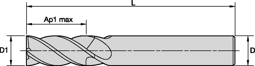
| [D1] Effective Cutting Diameter | 12 mm |
| [D1] Effective Cutting Diameter | 0.4724 in |
| [D] Adapter / Shank / Bore Diameter | 12 mm |
| [D] Adapter / Shank / Bore Diameter | 0.4724 in |
| [AP1MAX] 1st Maximum Cutting Depth | 30 mm |
| [AP1MAX] 1st Maximum Cutting Depth | 1.1811 in |
| [L3] Usable Length | 38 mm |
| [L3] Usable Length | 1.4961 in |
| [L] Overall Length | 83 mm |
| [L] Overall Length | 3.2677 in |
| [Z] Number of Flutes | 4 |
헬리컬 밀링램핑: 블랭크슬로팅: 스퀘어 엔드사이드 밀링/숄더 밀링: 스퀘어 엔드섕크 — 원통형 일반코너 스타일: 스퀘어 엔드이송 및 속도를 계산하려면 솔루션을 생성하세요.
솔루션 생성 후 이송 및 속도 아이콘을 선택하면 추천 값이 제공됩니다. 기계와 사양을 추가하여 사용자 정보를 지정하거나 슬라이더를 사용하여 조정할 수 있습니다.
| Adjustment factors for speed (Vc) and feed (Fz) • Metric | |||||||||||
| Ae/D1 | 2% | 4% | 5% | 8% | 10% | 12% | 20% | 30% | 40% | 50% | 100% |
| Kv | 2.1 - 3.6 | 1.6 - 3 | 1.6 - 2.5 | 1.6 | 1.4 | 1.38 | 1.3 | 1.2 | 1.1 | 1 | 1 |
| KFz | 3.58 | 2.56 | 2.3 | 1.84 | 1.67 | 1.54 | 1.25 | 1.09 | 1.02 | 1 | 0.9 |
| Note: Identify the radial engagement per percentage of the tool diameter (Ae/D1). That column will give you the factor to multiply the Base SMF and Base IPT on the Speed and Feed original table Kv = Factor to multiply the Speed by KFz = Factor to multiply the Feed by | |||||||||||
| To calculate application specific cutting data, please use Kv coefficient, and KFz from tables for adaption of cutting speeds and feeds respectively: Vc new = Vc * Kv IPT new = IPT * KFz | Sample Calculation Material: P5 D1: 14.0 mm Ae: 20% of D1 Recommended Speed Vc : 80 m/min Recommended Feed Fz: 0.063 mm/th Adjustment coefficient Kv : 1.30 Adjustment coefficient KFz : 1.25 | Final cutting data recommendation: Vc new = 80 * 1.30 = 104 m/min Fz new = 0.063 * 1.30 = 0.079 mm/th | |||||||||
| GOmill™ PRO • Regular • Recommended Starting Speed and Feed [Metric] | ||||||||||||||||||||
 |  |  | ||||||||||||||||||
| KCU25 | 날당 이송 fz(fz = mm/th) 는 사이드 밀링(A)용입니다. 슬로팅(B)의 경우 fz를 20%까지 줄이십시오. | |||||||||||||||||||
| 사이드 밀링 | 슬로팅 | 가공 속도 | D1 | |||||||||||||||||
| 소재 그룹 | ap | ae | ap | 최소 | 초기값 | 최대 | mm | 2,0 | 3,0 | 4,0 | 5,0 | 6,0 | 8,0 | 10,0 | 12,0 | 14,0 | 16,0 | 18,0 | 20,0 | 25,0 |
| P0 | Ap1 Max | 0,4 x D1 | 1,0 x D1 | 150 | 175 | 200 | fz | 0.014 | 0.021 | 0.028 | 0.036 | 0.044 | 0.060 | 0.072 | 0.083 | 0.092 | 0.101 | 0.108 | 0.114 | 0.124 |
| P1 | Ap1 Max | 0,4 x D1 | 1,0 x D1 | 150 | 175 | 200 | fz | 0.014 | 0.021 | 0.028 | 0.036 | 0.044 | 0.060 | 0.072 | 0.083 | 0.092 | 0.101 | 0.108 | 0.114 | 0.124 |
| P2 | Ap1 Max | 0,4 x D1 | 1,0 x D1 | 140 | 165 | 190 | fz | 0.014 | 0.021 | 0.028 | 0.036 | 0.044 | 0.060 | 0.072 | 0.083 | 0.092 | 0.101 | 0.108 | 0.114 | 0.124 |
| P3 | Ap1 Max | 0,4 x D1 | 1,0 x D1 | 120 | 140 | 160 | fz | 0.011 | 0.017 | 0.023 | 0.030 | 0.036 | 0.050 | 0.061 | 0.070 | 0.079 | 0.087 | 0.095 | 0.101 | 0.114 |
| P4 | Ap1 Max | 0,4 x D1 | 0,75 x D1 | 90 | 120 | 150 | fz | 0.010 | 0.016 | 0.021 | 0.027 | 0.033 | 0.045 | 0.054 | 0.062 | 0.070 | 0.077 | 0.083 | 0.088 | 0.098 |
| P5 | Ap1 Max | 0,4 x D1 | 1,0 x D1 | 60 | 80 | 100 | fz | 0.009 | 0.014 | 0.019 | 0.024 | 0.029 | 0.040 | 0.048 | 0.056 | 0.063 | 0.070 | 0.076 | 0.081 | 0.091 |
| P6 | Ap1 Max | 0,4 x D1 | 0,75 x D1 | 50 | 63 | 75 | fz | 0.008 | 0.012 | 0.016 | 0.020 | 0.025 | 0.034 | 0.040 | 0.047 | 0.052 | 0.057 | 0.061 | 0.065 | 0.071 |
| M1 | Ap1 Max | 0,4 x D1 | 1,0 x D1 | 90 | 103 | 115 | fz | 0.011 | 0.017 | 0.023 | 0.030 | 0.036 | 0.050 | 0.061 | 0.070 | 0.079 | 0.087 | 0.095 | 0.101 | 0.114 |
| M2 | Ap1 Max | 0,4 x D1 | 1,0 x D1 | 60 | 70 | 80 | fz | 0.009 | 0.014 | 0.019 | 0.024 | 0.029 | 0.040 | 0.048 | 0.056 | 0.063 | 0.070 | 0.076 | 0.081 | 0.091 |
| M3 | Ap1 Max | 0,4 x D1 | 1,0 x D1 | 60 | 65 | 70 | fz | 0.008 | 0.012 | 0.016 | 0.020 | 0.025 | 0.034 | 0.040 | 0.047 | 0.052 | 0.057 | 0.061 | 0.065 | 0.071 |
| K1 | Ap1 Max | 0,4 x D1 | 1,0 x D1 | 120 | 135 | 150 | fz | 0.014 | 0.021 | 0.028 | 0.036 | 0.044 | 0.060 | 0.072 | 0.083 | 0.092 | 0.101 | 0.108 | 0.114 | 0.124 |
| K2 | Ap1 Max | 0,4 x D1 | 1,0 x D1 | 110 | 125 | 140 | fz | 0.011 | 0.017 | 0.023 | 0.030 | 0.036 | 0.050 | 0.061 | 0.070 | 0.079 | 0.087 | 0.095 | 0.101 | 0.114 |
| K3 | Ap1 Max | 0,4 x D1 | 1,0 x D1 | 110 | 120 | 130 | fz | 0.009 | 0.014 | 0.019 | 0.024 | 0.029 | 0.040 | 0.048 | 0.056 | 0.063 | 0.070 | 0.076 | 0.081 | 0.091 |
| S1 | Ap1 Max | 0,4 x D1 | 0,3 x D1 | 50 | 70 | 90 | fz | 0.011 | 0.017 | 0.023 | 0.030 | 0.036 | 0.050 | 0.061 | 0.070 | 0.079 | 0.087 | 0.095 | 0.101 | 0.114 |
| S2 | Ap1 Max | 0,4 x D1 | 0,3 x D1 | 25 | 38 | 50 | fz | 0.006 | 0.009 | 0.013 | 0.016 | 0.019 | 0.026 | 0.032 | 0.037 | 0.042 | 0.046 | 0.050 | 0.054 | 0.061 |
| S3 | Ap1 Max | 0,4 x D1 | 1,0 x D1 | 25 | 33 | 40 | fz | 0.006 | 0.009 | 0.013 | 0.016 | 0.019 | 0.026 | 0.032 | 0.037 | 0.042 | 0.046 | 0.050 | 0.054 | 0.061 |
| S4 | Ap1 Max | 0,4 x D1 | 1,0 x D1 | 50 | 55 | 60 | fz | 0.007 | 0.011 | 0.016 | 0.021 | 0.026 | 0.037 | 0.045 | 0.052 | 0.058 | 0.064 | 0.069 | 0.074 | 0.084 |
| H1 | Ap1 Max | 0,4 x D1 | 0,75 x D1 | 80 | 110 | 140 | fz | 0.010 | 0.016 | 0.021 | 0.027 | 0.033 | 0.045 | 0.054 | 0.062 | 0.070 | 0.077 | 0.083 | 0.088 | 0.098 |
| H2 | Ap1 Max | 0,4 x D1 | 0,5 x D1 | 70 | 95 | 120 | fz | 0.008 | 0.012 | 0.016 | 0.020 | 0.025 | 0.034 | 0.040 | 0.047 | 0.052 | 0.057 | 0.061 | 0.065 | 0.071 |
| Lower value of cuting speed is used for high stock removal applications or for higher hardness (machinability) within group. Higher value of cuting speed is used for finishing applications or for lower hardness (machinability) within group. Above parameters are based on ideal conditions. For smaller taper machining centers, please adjust parameters accordiongly on diameters greater than 12mm. For better surface finish reduce feed per tooth. Side and Slotting milling aplications: for longest reach (L3) tools, reduce Ae by 30%. Sharp corner tools not recommended for sloting aplication. | ||||||||||||||||||||
| Adjustment factors for speed (Vc) and feed (Fz) • Metric | |||||||||||
| Ae/D1 | 2% | 4% | 5% | 8% | 10% | 12% | 20% | 30% | 40% | 50% | 100% |
| Kv | 2.1 - 3.6 | 1.6 - 3 | 1.6 - 2.5 | 1.6 | 1.4 | 1.38 | 1.3 | 1.2 | 1.1 | 1 | 1 |
| KFz | 3.58 | 2.56 | 2.3 | 1.84 | 1.67 | 1.54 | 1.25 | 1.09 | 1.02 | 1 | 0.9 |
| Note: Identify the radial engagement per percentage of the tool diameter (Ae/D1). That column will give you the factor to multiply the Base SMF and Base IPT on the Speed and Feed original table Kv = Factor to multiply the Speed by KFz = Factor to multiply the Feed by | |||||||||||
| To calculate application specific cutting data, please use Kv coefficient, and KFz from tables for adaption of cutting speeds and feeds respectively: Vc new = Vc * Kv IPT new = IPT * KFz | Sample Calculation Material: P5 D1: 14.0 mm Ae: 20% of D1 Recommended Speed Vc : 80 m/min Recommended Feed Fz: 0.063 mm/th Adjustment coefficient Kv : 1.30 Adjustment coefficient KFz : 1.25 | Final cutting data recommendation: Vc new = 80 * 1.30 = 104 m/min Fz new = 0.063 * 1.30 = 0.079 mm/th | |||||||||
| GOmill™ PRO • Long • Recommended Starting Speed and Feed [Metric] | ||||||||||||||||||
| | |||||||||||||||||
| KCU25 | 날당 이송 fz(fz = mm/th) 는 사이드 밀링(A)용입니다. 슬로팅(B)의 경우 fz를 20%까지 줄이십시오. | |||||||||||||||||
| 사이드 밀링 | 가공 속도 | D1 | ||||||||||||||||
| 소재 그룹 | ap | ae | 최소 | 초기값 | 최대 | mm | 2,0 | 3,0 | 4,0 | 5,0 | 6,0 | 8,0 | 10,0 | 12,0 | 14,0 | 18,0 | 20,0 | 25,0 |
| P0 | Ap1 Max | 0.2xD | 150 | 175 | 200 | fz | 0.014 | 0.021 | 0.028 | 0.036 | 0.044 | 0.060 | 0.072 | 0.083 | 0.092 | 0.108 | 0.114 | 0.124 |
| P1 | Ap1 Max | 0.2xD | 150 | 175 | 200 | fz | 0.014 | 0.021 | 0.028 | 0.036 | 0.044 | 0.060 | 0.072 | 0.083 | 0.092 | 0.108 | 0.114 | 0.124 |
| P2 | Ap1 Max | 0.2xD | 140 | 165 | 190 | fz | 0.014 | 0.021 | 0.028 | 0.036 | 0.044 | 0.060 | 0.072 | 0.083 | 0.092 | 0.108 | 0.114 | 0.124 |
| P3 | Ap1 Max | 0.2xD | 120 | 140 | 160 | fz | 0.011 | 0.017 | 0.023 | 0.030 | 0.036 | 0.050 | 0.061 | 0.070 | 0.079 | 0.095 | 0.101 | 0.114 |
| P4 | Ap1 Max | 0.2xD | 90 | 120 | 150 | fz | 0.010 | 0.016 | 0.021 | 0.027 | 0.033 | 0.045 | 0.054 | 0.062 | 0.070 | 0.083 | 0.088 | 0.098 |
| P5 | Ap1 Max | 0.2xD | 60 | 80 | 100 | fz | 0.009 | 0.014 | 0.019 | 0.024 | 0.029 | 0.040 | 0.048 | 0.056 | 0.063 | 0.076 | 0.081 | 0.091 |
| P6 | Ap1 Max | 0.15xD | 50 | 63 | 75 | fz | 0.008 | 0.012 | 0.016 | 0.020 | 0.025 | 0.034 | 0.040 | 0.047 | 0.052 | 0.061 | 0.065 | 0.071 |
| M1 | Ap1 Max | 0.2xD | 90 | 103 | 115 | fz | 0.011 | 0.017 | 0.023 | 0.030 | 0.036 | 0.050 | 0.061 | 0.070 | 0.079 | 0.095 | 0.101 | 0.114 |
| M2 | Ap1 Max | 0.2xD | 60 | 70 | 80 | fz | 0.009 | 0.014 | 0.019 | 0.024 | 0.029 | 0.040 | 0.048 | 0.056 | 0.063 | 0.076 | 0.081 | 0.091 |
| M3 | Ap1 Max | 0.2xD | 60 | 65 | 70 | fz | 0.008 | 0.012 | 0.016 | 0.020 | 0.025 | 0.034 | 0.040 | 0.047 | 0.052 | 0.061 | 0.065 | 0.071 |
| K1 | Ap1 Max | 0.2xD | 120 | 135 | 150 | fz | 0.014 | 0.021 | 0.028 | 0.036 | 0.044 | 0.060 | 0.072 | 0.083 | 0.092 | 0.108 | 0.114 | 0.124 |
| K2 | Ap1 Max | 0.2xD | 110 | 125 | 140 | fz | 0.011 | 0.017 | 0.023 | 0.030 | 0.036 | 0.050 | 0.061 | 0.070 | 0.079 | 0.095 | 0.101 | 0.114 |
| K3 | Ap1 Max | 0.2xD | 110 | 120 | 130 | fz | 0.009 | 0.014 | 0.019 | 0.024 | 0.029 | 0.040 | 0.048 | 0.056 | 0.063 | 0.076 | 0.081 | 0.091 |
| S1 | Ap1 Max | 0.1xD | 50 | 70 | 90 | fz | 0.011 | 0.017 | 0.023 | 0.030 | 0.036 | 0.050 | 0.061 | 0.070 | 0.079 | 0.095 | 0.101 | 0.114 |
| S2 | Ap1 Max | 0.1xD | 25 | 38 | 50 | fz | 0.006 | 0.009 | 0.013 | 0.016 | 0.019 | 0.026 | 0.032 | 0.037 | 0.042 | 0.050 | 0.054 | 0.061 |
| S3 | Ap1 Max | 0.1xD | 25 | 33 | 40 | fz | 0.006 | 0.009 | 0.013 | 0.016 | 0.019 | 0.026 | 0.032 | 0.037 | 0.042 | 0.050 | 0.054 | 0.061 |
| S4 | Ap1 Max | 0.15xD | 50 | 55 | 60 | fz | 0.007 | 0.011 | 0.016 | 0.021 | 0.026 | 0.037 | 0.045 | 0.052 | 0.058 | 0.069 | 0.074 | 0.084 |
| H1 | Ap1 Max | 0.15xD | 80 | 110 | 140 | fz | 0.010 | 0.016 | 0.021 | 0.027 | 0.033 | 0.045 | 0.054 | 0.062 | 0.070 | 0.083 | 0.088 | 0.098 |
| H2 | Ap1 Max | 0.15xD | 70 | 95 | 120 | fz | 0.008 | 0.012 | 0.016 | 0.020 | 0.025 | 0.034 | 0.040 | 0.047 | 0.052 | 0.061 | 0.065 | 0.071 |
| Lower value of cuting speed is used for high stock removal applications or for higher hardness (machinability) within group. Higher value of cuting speed is used for finishing applications or for lower hardness (machinability) within group. Above parameters are based on ideal conditions. For smaller taper machining centers, please adjust parameters accordiongly on diameters greater than 12mm. For better surface finish reduce feed per tooth. Side milling aplications: for longest reach (L3) tools, reduce Ae by 30%. Sharp corner tools not recommended for sloting aplication. | ||||||||||||||||||
| Angle of engagement (phi°) relative to cutting width (Ae) |  | ||||||||||
| ae | 2% | 4% | 5% | 8% | 10% | 12% | 20% | 30% | 40% | 50% | 100% |
| phi - angle of engagement | 16.26 | 23.07 | 25.84 | 32.86 | 36.87 | 40.54 | 53.13 | 66.42 | 78.46 | 90.00 | 180.00 |
I have read and accepted the Terms & Conditions of use


ISO 카탈로그 번호
ANSI 카탈로그 번호
to find similar products.Please select a file to download
Models
. Please enter the desired qty for the material(s) you want to include in your promotion or Proceed Without Promotion and only your base materials will be added to the cart.
Minimum quantity should be
| SAP Material Number | ISO 카탈로그 번호 | 등급 |
|---|
You are about to leave the Solution building process.
Are you sure you want to leave?